

Exhaust gas recirculation blower and internal combustion engine
Patent Information
- Authority / Receiving Office
- CN · China
- Patent Type
- Applications(China)
- Current Assignee / Owner
- MAN ENERGY SOLUTIONS SA
- Publication Date
- 2019-06-28
- Estimated Expiration
- Not applicable · inactive patent
Smart Images
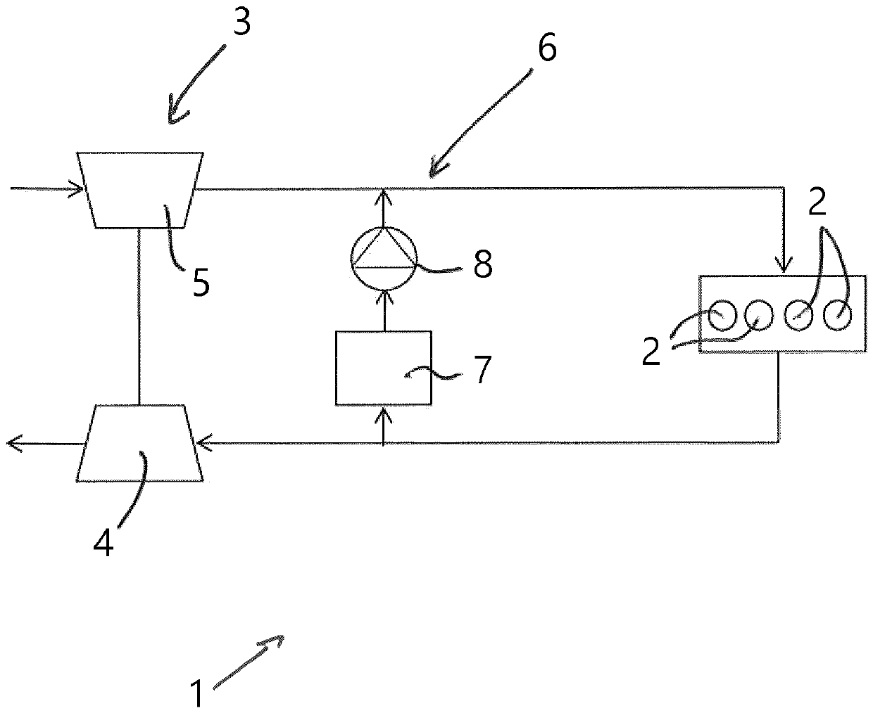
Figure 1
Abstract
Description
technical field
[0001] The invention relates to an exhaust gas recirculation blower and to an internal combustion engine. Background technique
[0002] Internal combustion engines with exhaust gas recirculation systems are well known to those skilled in the art to which this document is directed. In such internal combustion engines, it is known to extract the exhaust gas leaving the internal combustion engine from its exhaust gas branch and to blow the charge air along the engine's charge air via so-called exhaust gas recirculation blowers (also called EGR blowers) of the exhaust gas recirculation system. The exhaust gas is guided in the direction of the duct and then mixed with charge air to be supplied to the cylinders of the internal combustion engine.
[0003] Exhaust gas recirculation blowers or EGR blowers are typically embodied as turbo compressors, which compress the exhaust gases to a defined pressure. An exhaust gas recirculation blower of an exhaust gas recircul...