
Beverage cooling device and cooling method

A beverage cooling device and cooling device technology, applied in household refrigeration devices, lighting and heating equipment, household appliances, etc., can solve the problems of inability to quickly cool down beer, long cooling time, and poor taste

Pending Publication Date: 2019-06-28
NANJING CHUANGWEI HOUSEHOLD ELECTRONICS APPLIANCES LTD
View PDF0 Cites 1 Cited by
  • Summary
  • Abstract
  • Description
  • Claims
  • Application Information

AI Technical Summary

Problems solved by technology

[0002] If you want to drink iced drinks in summer, you can only put the drinks in the refrigerator, put them in the freezer or refrigerate them for a long time, and put the beer in the refrigerator to cool down. The disadvantage is that whether you put it in the freezer or the refrigerator, the cooling time is longer (more than 39min), unable to achieve rapid cooling of beer (within 5min)
[0003] Generally, if consumers want to cool their drinks quickly, they can only put ice cubes into the drink. Although this can quickly reduce the temperature of the drink, it is easy to dilute the drink and make it taste worse.

Method used


Image

  • Beverage cooling device and cooling method
  • Beverage cooling device and cooling method

Examples


Embodiment 1

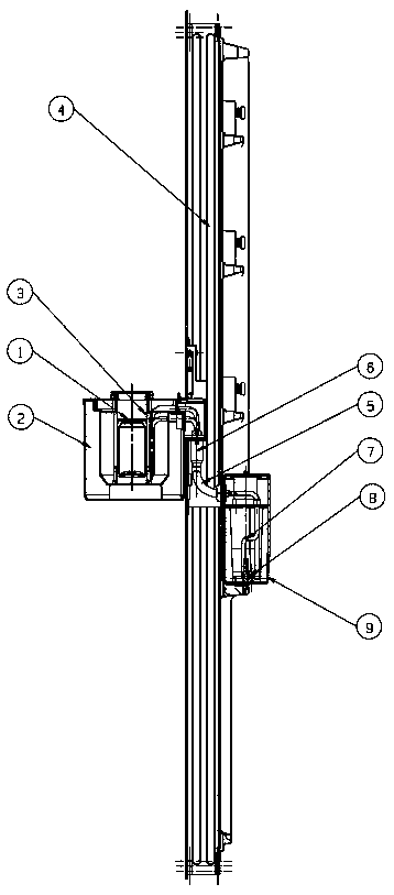
[0027] Such as figure 1 , figure 2 As shown, the present invention provides a beverage cooling device. The cooling device is installed on the refrigeration equipment. The pipes in the equipment door are connected;

[0028] The exterior is used to place beverages with outer packaging, and there is liquid refrigerant in the interior, and the embedded pipeline 5 together with the interior and exterior makes the exterior also have refrigerant to cool down the beverage.

[0029] Further, the inside is a refrigerant liquid storage box 9, and the bottom of the refrigerant liquid storage box 9 is provided with a submersible pump 8, which is connected to the refrigerant liquid conduit 7, and one end of the refrigerant liquid conduit 7 is connected to the embedded pipeline 5 Connected, the submersible pump 8 pumps the refrigerant liquid to the outside.

[0030] Further, the outside is a beverage cooling box, and a chamber for containing refrigerant liquid is arranged in the beverage...

Embodiment 2

[0036] Based on the above beverage cooling device, the present invention also provides a method for cooling beverages, which specifically includes the following steps.

[0037] 1. The refrigerating liquid is ethanol solution with a concentration of 40%~60%, placed in the refrigerating liquid storage container, and frozen to -18°C in the freezer compartment of the refrigerator (liquid state, not condensed);

[0038] 2. The submersible pump 8 is fixed at the bottom of the liquid storage box, placed in the refrigerant liquid, and the refrigerant liquid is discharged into the beer cooling box 2 through the refrigerant liquid conduit 7, the embedded pipeline 5 (placed in the door bubble layer), and the quick connector middle;

[0039] 3. The beer cooling box 2 is detachably hung outside the freezer door 4, and includes an inner box and an outer shell. There is a foam layer between the inner box and the outer shell. Two silicone sleeves 3 are fixed in the inner box, and two cans of...


PUM


Abstract

The invention provides a beverage cooling device and a cooling method. The cooling device is installed on refrigeration equipment, the cooling device comprises an inner part and an outer part, the inner part is located in the refrigeration equipment, the outer part is located outside the refrigeration equipment, and the inner part is connected to the outer part through a pipeline pre-buried in thedoor body of the refrigeration equipment; and the outer part is used for containing the beverage with an outside package, a liquid refrigerating fluid is arranged in the inner part, the pre-buried pipeline is used for communicating the inner part and the outer part, so that the refrigerating fluid is also contained in the outer part, and the beverage is cooled. According to the device and the method, the cooling structure is simple, the beverage can be cooled conveniently and quickly by adopting the cooling method based on the device, so that the beverage can be rapidly cooled.

Description

technical field [0001] The patent of this invention relates to a rapid cooling technology for beer / beverages, which is mainly used in the field of refrigerators and can also be extended to other refrigeration equipment. Background technique [0002] If you want to drink iced drinks in summer, you can only put the drinks in the refrigerator, put them in the freezer or refrigerate them for a long time, and put the beer in the refrigerator to cool down. The disadvantage is that whether you put it in the freezer or the refrigerator, the cooling time is longer (above 39min), unable to achieve rapid cooling of beer (within 5min). [0003] General consumers can only put ice cubes into the beverage if they want to quickly cool the beverage. Although this can quickly reduce the temperature of the beverage, it will easily dilute the beverage and make it worse in taste. Contents of the invention [0004] Aiming at the above-mentioned problems in the prior art, the present invention ...

Claims


Application Information

Patent Timeline
IPC IPC(8): F25D31/00
Inventor 文坚刘晓庆谷宇张海潮李之龙吴启楠
Owner NANJING CHUANGWEI HOUSEHOLD ELECTRONICS APPLIANCES LTD
Learn More