Rigid body generation method, rigid body generation device, rigid body generation equipment and storage medium

A rigid body and mean square error technology, applied in the field of optical tracking, can solve problems that affect the overall performance and robustness of the tracking system, low accuracy, and difficult to distinguish rigid bodies.

Active Publication Date: 2019-06-28
SHANGHAI GRAPHIC DIGITAL INFORMATION CO LTD
View PDF3 Cites 3 Cited by
  • Summary
  • Abstract
  • Description
  • Claims
  • Application Information

AI Technical Summary

Problems solved by technology

When the spatial position structure of the marker points in the target rigid body is the same or similar, it is difficult to distinguish between the rigid bodies, resulting in low accuracy when tracking multiple target rigid bodies, affecting the overall performance and robustness of the tracking system

Method used


Image

  • Rigid body generation method, rigid body generation device, rigid body generation equipment and storage medium
  • Rigid body generation method, rigid body generation device, rigid body generation equipment and storage medium
  • Rigid body generation method, rigid body generation device, rigid body generation equipment and storage medium

Examples


Embodiment 1

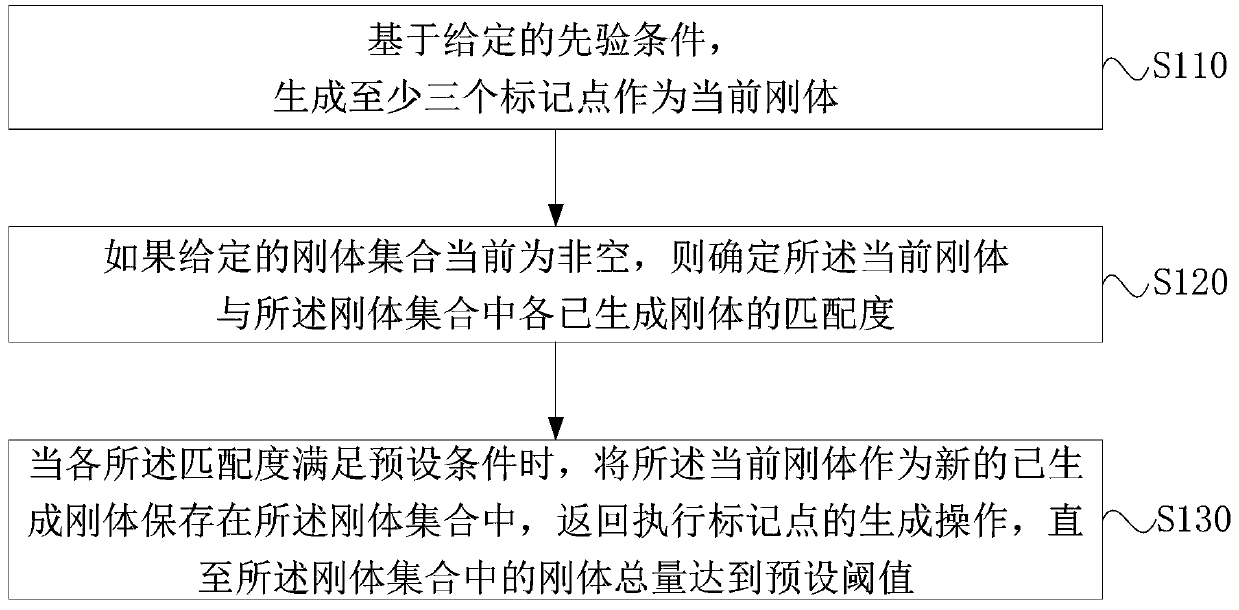
[0040] figure 1 It is a flow chart of a rigid body generation method provided by Embodiment 1 of the present invention. This embodiment is applicable to the situation where a rigid body is generated for a target object during optical tracking. Specifically, the method for generating a rigid body may be performed by a rigid body generating device, which may be implemented by means of software and / or hardware, and integrated into the device. Further, the devices include, but are not limited to: electronic devices such as computers, industrial computers, and medical equipment.

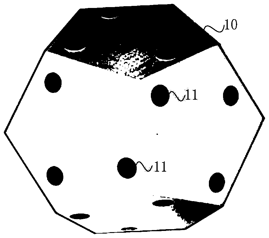
[0041] figure 2 It is a schematic diagram of the application scene of the rigid body generation method in Embodiment 1 of the present invention. Such as figure 2 As shown, to perform infrared optical tracking on the target object 10, a certain number of marker points 11 are first generated according to the structure of the target object 10. The marker points (Marker) are also called tracking balls, ...

Embodiment 2

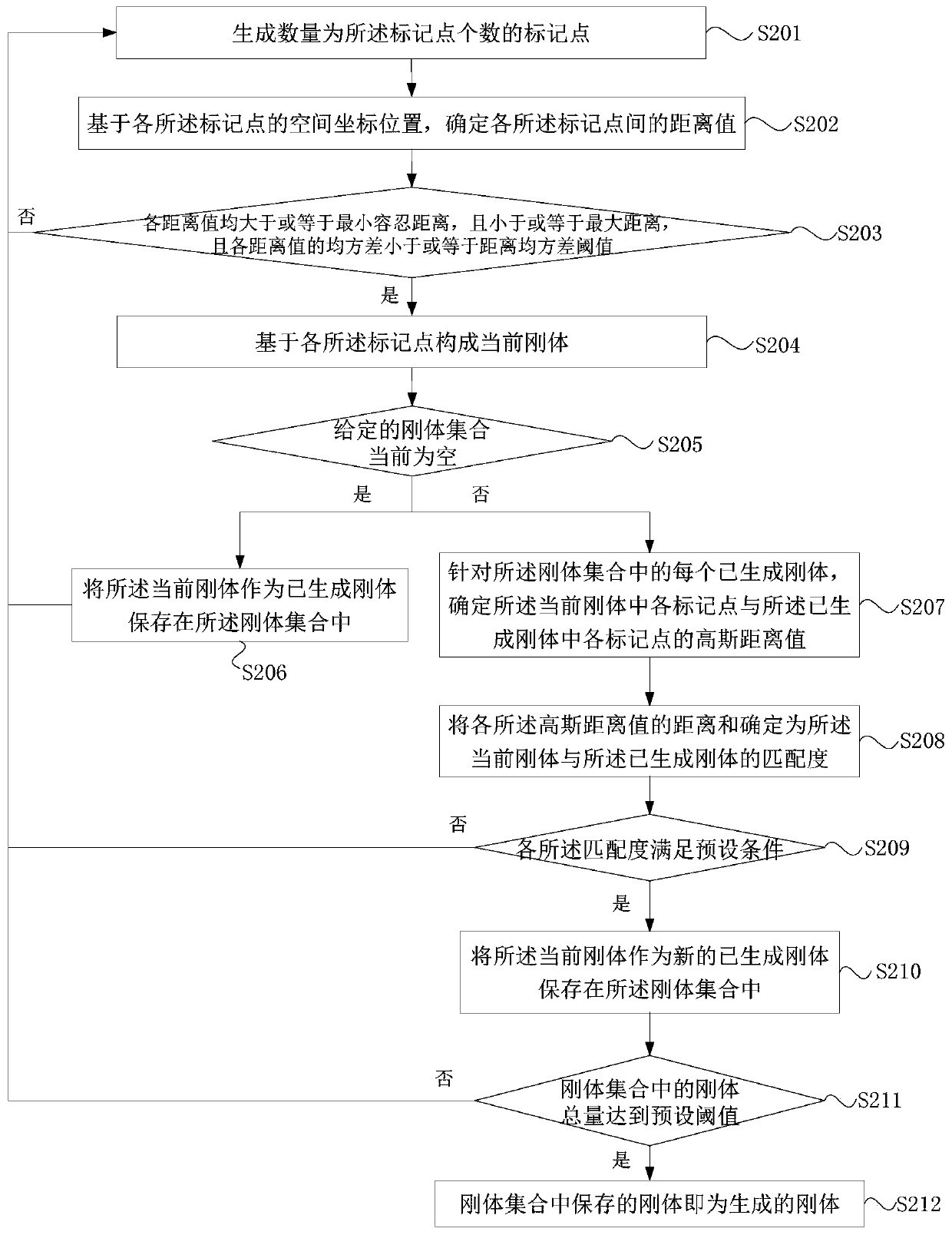
[0056] image 3 It is a flow chart of a rigid body generation method provided by Embodiment 2 of the present invention. This embodiment is specifically optimized on the basis of the foregoing embodiments. This embodiment specifically describes the process of determining the matching degree and judging whether the matching degree satisfies a preset condition. It should be noted that for technical details not exhaustively described in this embodiment, reference may be made to any of the foregoing embodiments.

[0057] Specifically, refer to image 3 , the method specifically includes the following steps:

[0058] S201. Generate marking points whose number is the number of marking points.

[0059] Exemplarily, the marker points are randomly generated according to the number of marker points to be generated (expressed as m), and then it is judged whether the distance value between each marker point meets the requirement of the prior condition for distance, only the marker poin...

Embodiment 3

[0094] Figure 4 It is a structural diagram of a rigid body generation device provided by Embodiment 3 of the present invention. The rigid body generating device provided in this embodiment includes:

[0095] A marker point generating module 310, configured to generate at least three marker points as the current rigid body based on a given prior condition;

[0096] A matching degree determination module 320, configured to determine the matching degree between the current rigid body and each generated rigid body in the rigid body set if the given rigid body set is currently non-empty;

[0097] The rigid body saving module 330 is configured to save the current rigid body as a new generated rigid body in the rigid body set when the matching degrees meet the preset conditions, and return to execute the generation operation of the marker points until the rigid body The total amount of rigid bodies in the collection reaches a preset threshold.

[0098] A rigid body generation dev...


PUM


Abstract

The invention discloses a rigid body generation method and device, equipment and a storage medium, and the method comprises the steps: generating at least three mark points as a current rigid body based on a given prior condition; if the given rigid body set is not null at present, determining the matching degree of the current rigid body and each generated rigid body in the rigid body set; and when each matching degree satisfies a preset condition, storing the current rigid body as a new generated rigid body in the rigid body set, and returning to execute a generation operation of a mark point until the total amount of the rigid bodies in the rigid body set reaches a preset threshold value. By adopting the technical scheme, the structural difference between the rigid bodies is ensured, and the tracking accuracy is improved.

Description

technical field [0001] Embodiments of the present invention relate to the technical field of optical tracking, and in particular, to a rigid body generation method, device, equipment, and storage medium. Background technique [0002] Infrared optical tracking technology has been widely used in medicine, UAV positioning, virtual reality and other fields. It is strongly reflective under infrared light, so that the spatial position information of the marked point can be extracted to realize the tracking of the target object. [0003] In an infrared optical tracking system, generally three marker points or more than three point clouds with a fixed spatial structure are defined as a rigid body, and the rigid body is attached to the target object as the target rigid body for tracking. When the spatial position structure of the marker points in the target rigid body is the same or similar, it is difficult to distinguish between the rigid bodies, resulting in low accuracy when trac...

Claims


Application Information

Patent Timeline
Patent Type & Authority Applications(China)
IPC IPC(8): G06T17/10
Inventor 周清会袁鑫毛佳红
Owner SHANGHAI GRAPHIC DIGITAL INFORMATION CO LTD
Why Eureka
Try Eureka