A vehicle balance suspension assembly structure

A technology for balancing suspension and assembly structure, applied in the direction of suspension, vehicle spring, elastic suspension, etc., can solve the problem of the large size and weight of the transition piece, the large change of the axle and frame structure, and the arrangement of the thrust rod mechanism. Difficulties and other problems, to achieve the effect of improving reliability and service life, improving adaptability to modification, and light weight

Active Publication Date: 2021-09-21
SHAANXI HEAVY DUTY AUTOMOBILE
View PDF7 Cites 0 Cited by
  • Summary
  • Abstract
  • Description
  • Claims
  • Application Information

AI Technical Summary

Problems solved by technology

[0003] Due to the existence of the steering device, there is a certain height difference between the upper and lower frames of the shaft-steering drawbar trailer, and the front and rear suspensions are installed on the lower frame and the upper frame respectively. For a three-axle off-road trailer, if the rear The suspension directly uses the balance suspension of the prior art, which will cause the size and weight of the transition piece between the suspension and the vehicle frame to be relatively large, which will affect the performance of the vehicle, and the arrangement of the thrust rod mechanism will be very difficult, which is very difficult for existing vehicles. The structure of the bridge and the frame has been greatly changed, and the versatility is poor

Method used


Image

  • A vehicle balance suspension assembly structure
  • A vehicle balance suspension assembly structure
  • A vehicle balance suspension assembly structure

Examples


Embodiment Construction

[0029] The present invention is described in further detail below in conjunction with accompanying drawing:

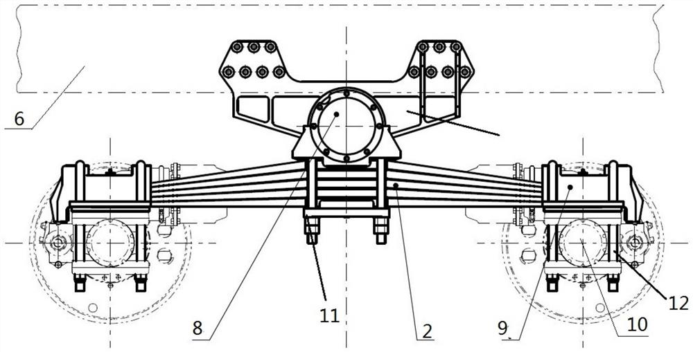
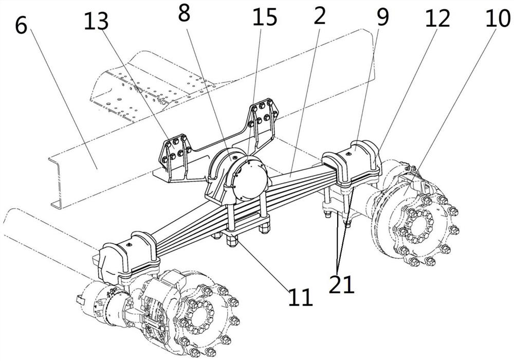
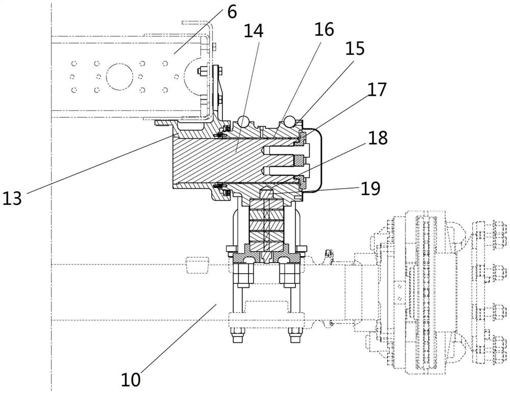
[0030] Such as Figure 1 to Figure 4 As shown, a vehicle balance suspension assembly structure includes a balance shaft end assembly 8, a leaf spring 2 and a bridge end assembly 9; both ends of the leaf spring 2 are fixed to the upper end of the vehicle axle 10 through the bridge end assembly 9; The balance shaft end assembly 8 includes a balance shaft support 13, a balance shaft 14 and a balance shaft housing 15, the balance shaft housing 15 and the balance shaft support 13 are provided with balance shaft installation holes, and the balance shaft housing 15 passes through the balance shaft 14 Rotately connected with the balance shaft support 13, the balance shaft support 13 is fixed on the vehicle frame 6, and the balance shaft housing 15 is fixed on the upper end of the leaf spring 2; when the height distance between the vehicle axle 10 and the vehicle frame 6 is con...


PUM


Abstract

The invention discloses a balance suspension assembly structure for a vehicle. The vehicle frame is used as the carrier of the suspension system. Both ends of the leaf spring are fixed on the upper end of the vehicle axle through the bridge end assembly. Installed at the lower end of the balance shaft housing, when the height distance between the axle and the frame is constant, the size and weight of the balance shaft support can be optimized, reducing the curb weight. At the same time, the weight is reduced by The frame is transmitted to the balance shaft housing, and then to the leaf spring and the axle, which reduces the force on the fixed connection between the balance shaft housing and the leaf spring, and is not affected by the load, greatly improving its reliability and service life ;This device adopts the balance shaft shaft end assembly to connect the leaf spring and the frame in rotation, which has the ability of traditional balance suspension to adapt to uneven road surfaces, increases the relative rotation height between the two axles, and can adapt to complex off-road road surfaces. Simple, lightweight, and highly versatile.

Description

technical field [0001] The invention relates to a leaf spring balance suspension assembly, in particular to a vehicle balance suspension assembly structure. Background technique [0002] At present, the suspension of trailers mostly adopts the leaf spring type with high stiffness and small dynamic deflection, which is mainly used for material transportation on good road surfaces, and it is difficult to meet the suspension performance requirements of off-road roads. And the existing leaf spring balance suspension assembly such as Figure 5 As shown in the schematic diagram of the traditional balance suspension, it is mainly composed of balance shaft assembly 1, leaf spring 2, lower thrust rod 3, axle 4, upper thrust rod 5, frame 6 and U-shaped bolt 7, and the leaf spring 2 passes through the U-shaped The bolt 7 is installed on the balance shaft assembly 1, and its two sides are matched with the slide plate seat of the axle 4 respectively, without longitudinal limit. The axle ...

Claims


Application Information

Patent Timeline
Patent Type & Authority Patents(China)
IPC IPC(8): B60G11/10
CPCB60G11/10B60G2202/112
Inventor 钟瑞聂文福叶智博姚旿冰曲学春傅耀宇
Owner SHAANXI HEAVY DUTY AUTOMOBILE
Why Eureka
Try Eureka