
Pressure assembly of automatic mechanical locking box, and hoisting device of box

An automatic mechanical and pressure technology, applied in the direction of transportation and packaging, cranes, trolley cranes, etc., can solve the problems of low automation and poor safety in box hoisting, and achieve structural locking prevention, self-locking and unlocking speed Fast, the effect of improving the unlocking speed

Active Publication Date: 2019-07-05
SOUTHWEST JIAOTONG UNIV
View PDF1 Cites 0 Cited by
  • Summary
  • Abstract
  • Description
  • Claims
  • Application Information

AI Technical Summary

Problems solved by technology

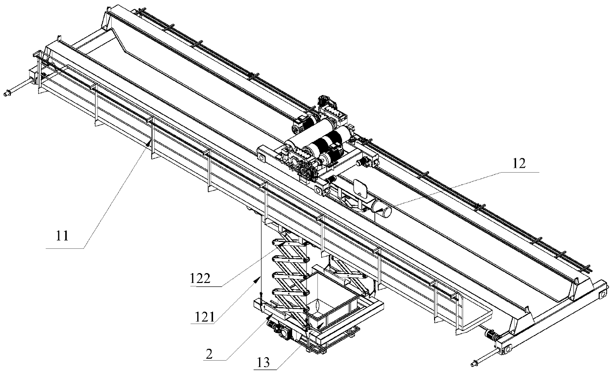
[0003] The main purpose of the present invention is to provide the pressure assembly of the automatic mechanical locking box and the hoisting device of the box, so as to solve the technical problems of low automation and poor safety in box hoisting in the prior art

Method used


Image

  • Pressure assembly of automatic mechanical locking box, and hoisting device of box
  • Pressure assembly of automatic mechanical locking box, and hoisting device of box
  • Pressure assembly of automatic mechanical locking box, and hoisting device of box

Examples


Embodiment Construction

[0033] The present invention will be clearly and completely described below in conjunction with the accompanying drawings. Those skilled in the art will be able to implement the present invention based on these descriptions. Before the present invention is described in conjunction with the accompanying drawings, it should be pointed out that:

[0034] The technical solutions and technical features provided in each part of the present invention, including the following description, can be combined with each other under the condition of no conflict.

[0035] In addition, the embodiments of the present invention referred to in the following description are generally only some embodiments of the present invention, not all of them. Therefore, based on the embodiments of the present invention, all other embodiments obtained by persons of ordinary skill in the art without creative efforts shall fall within the protection scope of the present invention.

[0036] About terms and unit...


PUM


Abstract

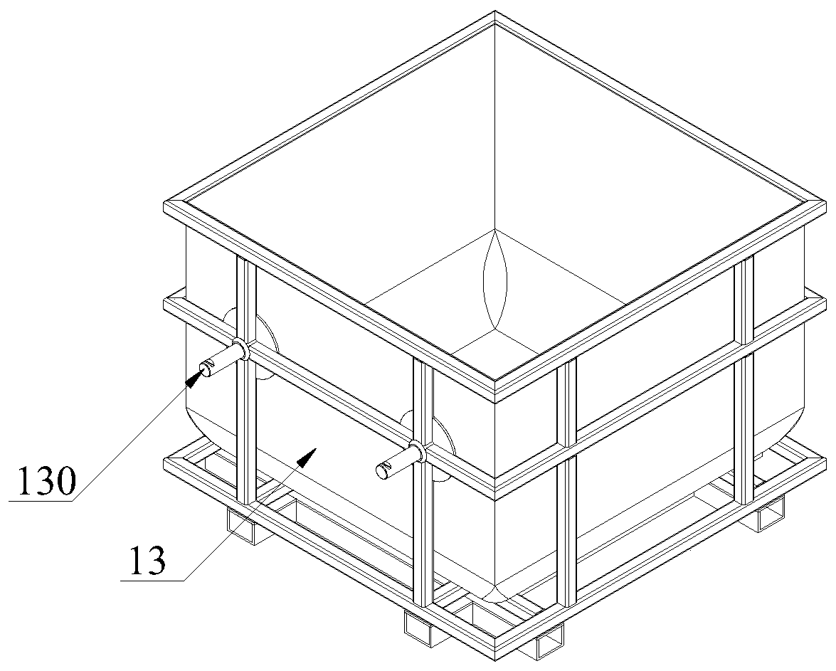
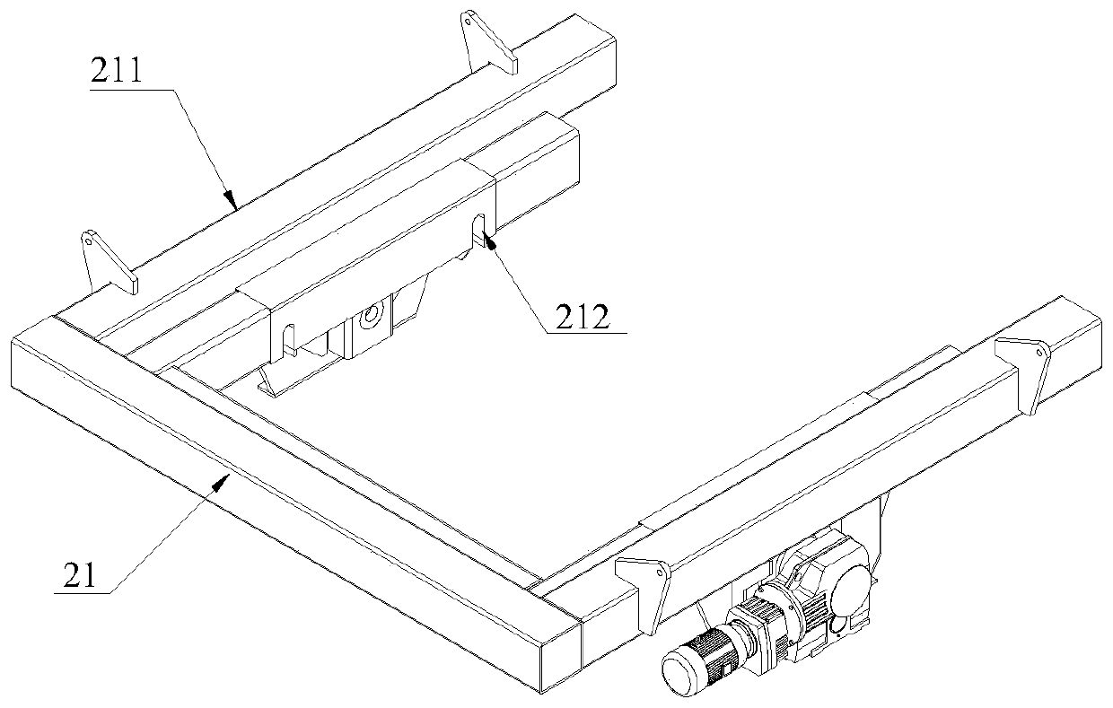
The invention discloses a pressure assembly of an automatic mechanical locking box. The pressure assembly comprises a set of convex rods which are connected with the exteriors of a set of opposite side faces of the box, a frame matched with the box, a C-shaped groove formed in the frame, and a pressure mechanism arranged in a frame supporting rod; the C-shaped groove comprises a first through holeand a second through hole; the pressure mechanism comprises a lower movable rod, a lower end pressure structure, an upper movable rod, an upper end pressure structure, an elastic part, a locking structure, a transmission structure and a straight tooth rod; the locking structure comprises a fixing part for limiting upward moving of the elastic part, and a convex strip arranged in the axial direction of the upper movable rod; the lower end pressure structure comprises a first matched end face and a first strip-shaped hole or a first strip-shaped groove; and the upper end pressure structure comprises a second matched end face and a second strip-shaped hole or a second strip-shaped groove. Self-locking and unlocking structures are pure mechanical structures, automatic self-locking and unlocking can be achieved, the efficiency is high, energy consumption is low, and safety is high.

Description

technical field [0001] The invention relates to the technical field of box body transportation, in particular to a pressure assembly for automatic mechanical locking of the box body and a lifting device for the box body. Background technique [0002] At present, the devices used for box-type lifting or handling mainly rely on manual auxiliary connections or external power-driven connections for operation. Human, material and financial resources, and low security, low degree of automation. For example, the Chinese invention patent with the publication number CN108584717A discloses a top-hanging container handling machine, which uses a lateral connecting frame fixed at the top corner position outside the top operating frame to connect the lifting electric winch, and the electric winch and the sling drive the top The bottom hook at the lower end of the operating frame lifts the container. The top-hanging container handling machine still needs a lot of manual and external force...

Claims


Application Information

Patent Timeline
Patent Type & Authority Applications(China)
IPC IPC(8): B66C19/00B66C11/16
CPCB66C19/00B66C11/16
Inventor 张则强王沙沙刘俊琦谢梦柯蒋晋李云鹏程文明
Owner SOUTHWEST JIAOTONG UNIV
Learn More