Multi-column eccentric compressing shrapnel bonding device and method
A technology for compressing shrapnel and bonding device, which is applied in the direction of ammunition, weapon accessories, offensive equipment, etc., can solve the problems of many operation steps, low shrapnel bonding efficiency, complex equipment structure, etc., to improve the fault tolerance rate and increase the shrapnel arrangement. The effect of density and promotion value
- Summary
- Abstract
- Description
- Claims
- Application Information
AI Technical Summary
Problems solved by technology
Method used
Image
Examples
Embodiment 1
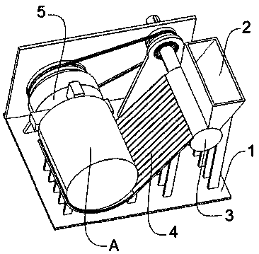
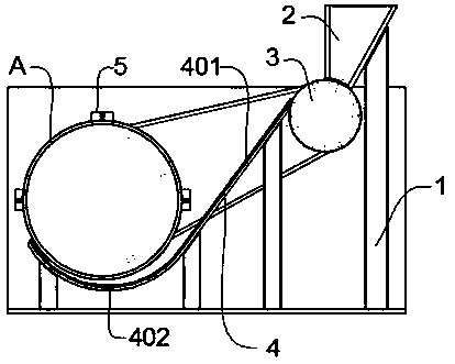
[0035] refer to figure 1 , figure 2 As shown, one embodiment of the present invention is a multi-row eccentrically compressed shrapnel bonding device, including a bracket 1, a shrapnel receiver 2 is provided on the bracket 1, and the shrapnel receiver 2 is used to store shrapnel, and the shrapnel The outlet of the receiver 2 is provided with a magnetic cylinder 3 for rotation. There is a gap between the above-mentioned shrapnel receiver 2 and the magnetic cylinder 3. An output track 4 is provided on one side of the above-mentioned magnetic cylinder 3. The head end of the above-mentioned output track 4 is connected to the The magnetic cylinder 3 is tangent, and the above-mentioned support 1 is provided with a chuck 5, which is used to install the cartridge case by the chuck 5, and the end of the above-mentioned output track 4 is used to be close to the cartridge case, so that the shrapnel is bonded to the cartridge case along the output track 4. The shrapnel receiver 2, the m...
Embodiment 2
[0041] Based on the above-mentioned embodiment, another embodiment of the present invention is that the above-mentioned output track 4 includes a straight track plate 401 and a circular track plate 402, the above-mentioned straight track plate 401 is tangent to the magnetic cylinder 3, and the end of the above-mentioned straight track plate 401 is provided with Circular track plate 402, the end of the above-mentioned circular track plate 402 is used to be close to the cartridge case;
[0042] Wherein, the head end of the straight track plate 401 is close to the magnetic cylinder 3, and the distance between the magnetic cylinder 3 and the straight track plate 401 is less than a shrapnel thickness, which is used for the shrapnel to fall into the straight track plate 401 during the continuous rotation of the magnetic cylinder 3; The cartridge case A is close to the end of the circular track plate 402, and there is a gap between the circular track plate 402 and the cartridge case A...
Embodiment 3
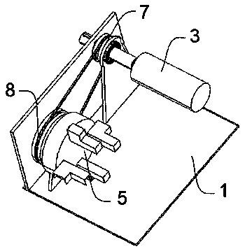
[0051] Based on the above examples, refer to image 3 As shown, the lower end of the above-mentioned shrapnel receiver 2 is provided with at least two split cylinders 6, and the gap between two adjacent split cylinders 6 is the same, and the shrapnel is resisted by the split cylinders 6, and the shrapnel is moved by the shrapnel receiver 2. During the process of falling into the magnetic cylinder 3, the dividing cylinder 6 limits the width of the disorderly arranged shrapnel in the shrapnel receiver 2 to prevent the shrapnel from falling arbitrarily.
[0052] Further, in order to ensure that the shrapnel will not fall off randomly from the shrapnel receiver 2, the gap between the front end of the shrapnel receiver 2 and the magnetic cylinder 3 is greater than or equal to the height of the shrapnel, and the rear end of the shrapnel receiver 2 and the magnetic cylinder 3 The gap between them is less than the height of the shrapnel.
[0053] The shrapnel is released through the ...
PUM
 Abstract
Description
Claims
Application Information
 - R&D
- Intellectual Property
- Life Sciences
- Materials
- Tech Scout
- Unparalleled Data Quality
- Higher Quality Content
- 60% Fewer Hallucinations
Browse by: Latest US Patents, China's latest patents, Technical Efficacy Thesaurus, Application Domain, Technology Topic, Popular Technical Reports.
© 2025 PatSnap. All rights reserved.Legal|Privacy policy|Modern Slavery Act Transparency Statement|Sitemap|About US| Contact US: help@patsnap.com


