
Wireless intelligent socket

A smart socket and wireless technology, which is applied to electrical components, coupling devices, circuits, etc., can solve the problems of burning sockets and high current of smart sockets, and achieve the effect of avoiding excessive instantaneous current

Inactive Publication Date: 2019-07-05
XIAN ZHISHENG RUIXIN SEMICON TECH CO LTD
View PDF0 Cites 0 Cited by
  • Summary
  • Abstract
  • Description
  • Claims
  • Application Information

AI Technical Summary

Problems solved by technology

[0004] However, when this kind of smart socket is in use, it is difficult to know the power consumption of the equipment connected to the socket in real time and exactly through the wireless terminal. , the equipment connected to the switch is charged and starts to operate at the same time, which may cause the current of the smart socket to be too large instantaneously, causing safety accidents such as burning the socket

Method used


Image

  • Wireless intelligent socket
  • Wireless intelligent socket

Examples


Embodiment 1

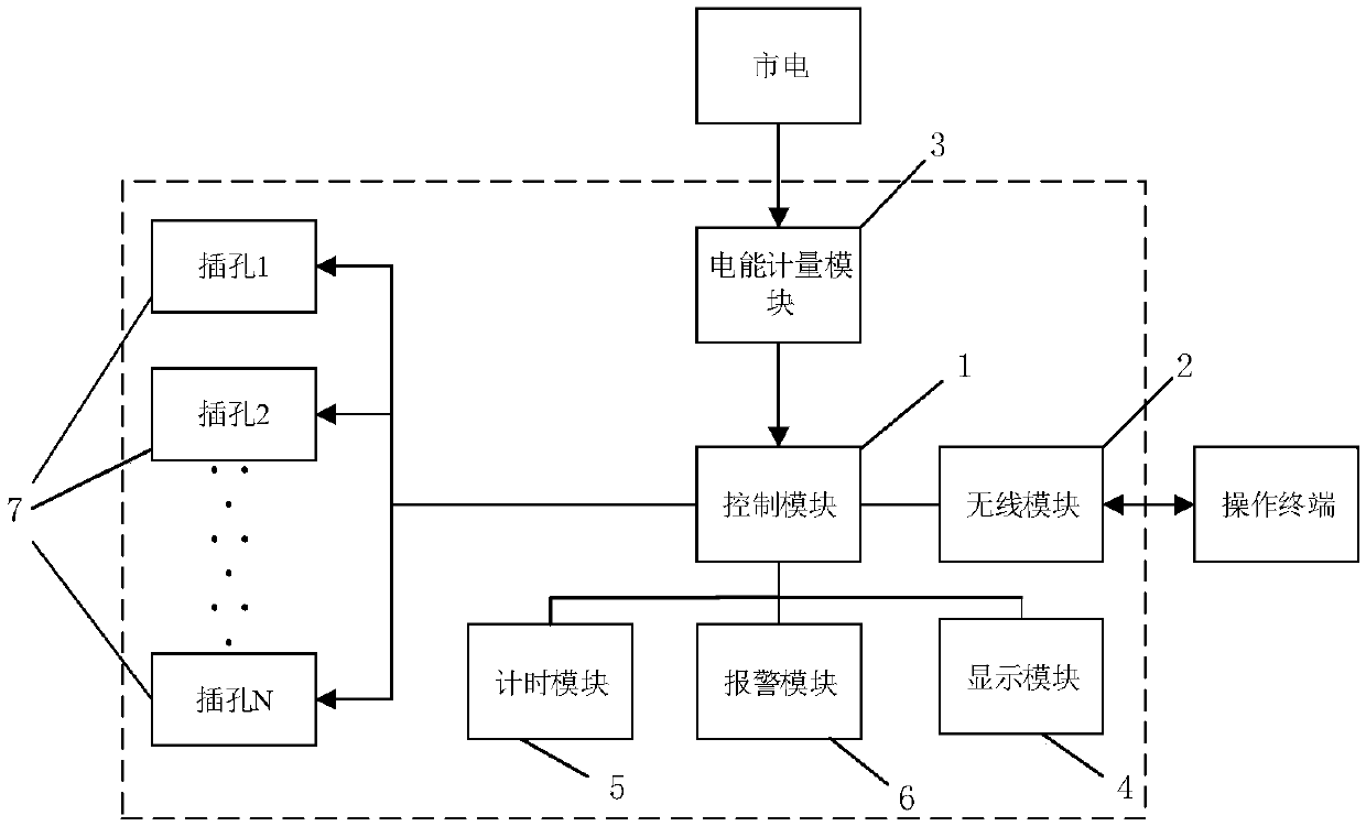
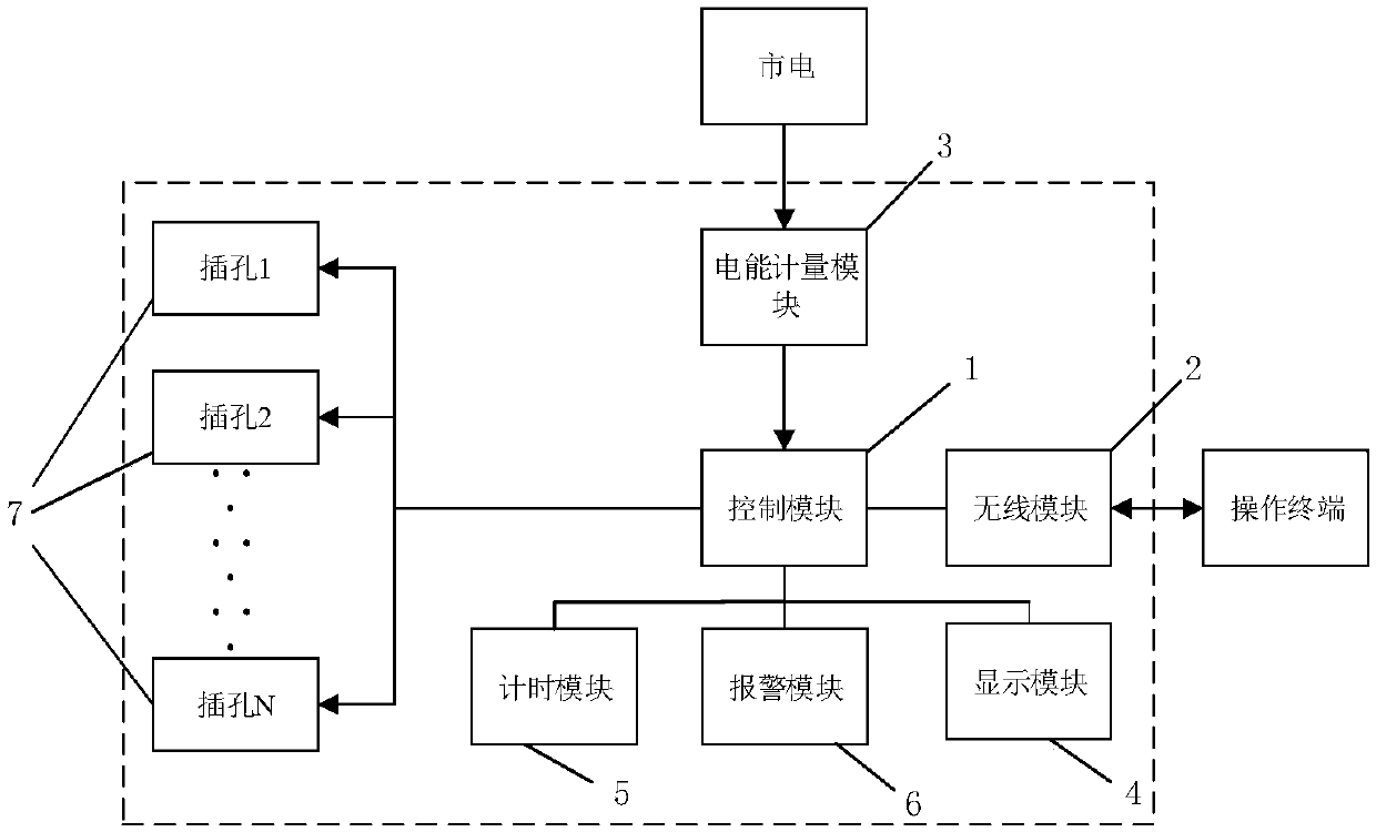
[0021] see figure 1 , figure 1 It is a schematic diagram of the connection of the wireless smart socket provided by the present invention. A wireless smart socket, comprising: a control module 1, a wireless module 2, an electric energy metering module 3, a display module 4, a timing module 5, an alarm module 6 and a jack 7, wherein,

[0022] The input end of the electric energy metering module 3 is connected to the mains; the first output end of the electric energy metering module 3 is connected to the second port of the control module 1; the second output end of the electric energy metering module 3 is connected to the alarm module 6 The first input terminal is connected; the output terminal of the alarm module 6 is connected with the fifth port of the chip; the third port of the control module 1 is connected with the display module 4; the fourth port of the control module 1 is connected with the The input end of the timing module 5 is connected; the output end of the timin...

Embodiment 2

[0029] read on figure 1 , this embodiment is described in detail on the basis of the foregoing embodiments. The present invention provides a wireless intelligent socket, comprising: a control module 1 , a wireless module 2 , an electric energy metering module 3 , a display module 4 , a timing module 5 , an alarm module 6 and a socket 7 . In order to make people's lives more convenient, it is possible to know the power consumption of the equipment connected to the socket through the wireless terminal in real time, and to use the wireless smart socket more safely, so as to use the socket. The smart socket has at least two jacks 7. When using the socket, each device is connected to the smart socket through the jacks 7, and the user can establish a connection with the wireless module 2 of the smart socket through the smart terminal, and then pass Wirelessly control the outlet to turn it on, off, and view power consumption.

[0030] Preferably, the control module 1 further includ...


PUM


Abstract

The present invention concretely relates to a wireless intelligent socket. The socket comprises a control module 1, a wireless module 2, an electric energy metering module 3, a display module 4, a timing module 5, an alarm module 6 and a jack 7. The input end of the electric energy metering module 3 is connected with an electric supply; the second output end of the electric energy metering module3 is connected with the input end of the alarm module 6; the output end of the timing module 5 is connected with the jack 7; and the wireless module 2, the electric energy metering module 3, the display module 4 and the input end of the timing module 5 are connected, and the alarm module 6 are connected with the first port, the second port, the third port, the fourth port and the fifth port of thecontrol module. The wireless intelligent socket can timely check the power consumption condition of the device through wireless control and can avoid intelligent disconnection when over-load is generated so as to avoid accidents and avoid that all the devices are opened at the same time to cause a large current to burn the socket or cause fire.

Description

technical field [0001] The invention belongs to the field of smart home, and in particular relates to a wireless smart socket. Background technique [0002] Socket claims again supply socket and combined socket and switch, refers to the insertable seat of one or more circuit connections, can insert various wiring by it, is convenient to connect with other circuits. The power socket is an electrical device that provides a power interface for household appliances, and it is also an electrical accessory that is used more in residential electrical design. It has a very close relationship with people's lives. [0003] At present, the automation of household smart appliances or smart home can cover various products used in people's daily life. With the development of radio networks and the popularization of mobile devices, there have been smart sockets that can be controlled on and off by mobile phones or tablets. Moreover, this smart socket also has a timer switch function, whic...

Claims


Application Information

Patent Timeline
Patent Type & Authority Applications(China)
IPC IPC(8): H01R13/66H01R13/70H01R13/713
CPCH01R13/66H01R13/665H01R13/6683H01R13/6691H01R13/70H01R13/713
Inventor 李创波
Owner XIAN ZHISHENG RUIXIN SEMICON TECH CO LTD
Learn More