
On-vehicle power grid management system and method of use thereof

A management system and on-board power grid technology, applied in the field of on-board power grid management, can solve problems such as battery internal resistance increase, short circuit, equipment damage, etc.

Active Publication Date: 2020-04-14
DALIAN ROILAND SCI & TECH CO LTD
View PDF6 Cites 0 Cited by
  • Summary
  • Abstract
  • Description
  • Claims
  • Application Information

AI Technical Summary

Problems solved by technology

[0004] 1. It is inaccurate to judge the battery status by monitoring the battery voltage value:
[0005] The battery will slowly age over time. If it is used improperly or ignited too frequently, the battery will age faster, and the internal resistance of the aged battery will increase. The result is that the voltage measured when the battery has lost power is still very High, the central electrical control unit will misjudge that the battery is still in a normal state, and continue to maintain the current power consumption management, resulting in a serious battery loss
[0006] 2. It is impossible to monitor the power consumption of each electrical equipment in real time and accurately:
[0008] 3. The power supply control is very strong, and it is impossible to achieve precise control:
[0009] A power supply control switch often controls the power supply of multiple electrical equipment. If the switch is turned off, it will cause multiple electrical equipment to be powered off.
[0010] 4. It is impossible to monitor the power loss on the power supply line and connectors in real time and accurately:
[0011] The power supply line will slowly age over time, the outer insulation layer may fall off, and it will cause a short circuit or leakage if it is connected to other conductors
The mechanical contacts of the connector will be oxidized or have poor contact after long-term use, resulting in increased resistance
These will cause the loss of electric energy and even the damage of equipment, and the spontaneous combustion of vehicles.

Method used


Image

  • On-vehicle power grid management system and method of use thereof

Examples


Embodiment 1

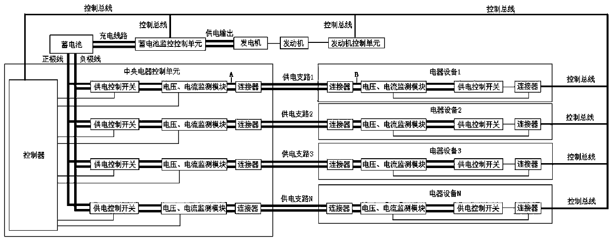
[0050] This embodiment provides a vehicle power grid management system, including: a central electrical control unit, a battery, a battery monitoring control unit, a generator, an engine, an engine control unit, and an electrical equipment unit. The central electrical control unit communicates with the battery through a control bus , the battery monitoring control unit, the engine control unit, and the electrical equipment unit are connected. The equipment unit is connected.

[0051] The central electrical control unit realizes the switch control of each power supply and the management of electric load;

[0052] The power supply control switch controls the opening and closing of the power supply and is controlled by the central electrical control unit;

[0053] The generator, driven by the engine, realizes the conversion of mechanical energy into electrical energy, supplies power for the electrical equipment of the whole vehicle and charges the battery;

[0054] storage batt...

Embodiment 2

[0059]This embodiment provides another vehicle-mounted power grid management system, including: a central electrical control unit, a battery, a battery monitoring control unit, a generator, an engine, an engine control unit, and an electrical equipment unit. The central electrical control unit communicates with the The battery, the battery monitoring control unit, the engine control unit, and the electrical equipment unit are connected. The battery monitoring control unit is connected to the battery and the generator respectively. The engine is connected to the generator and the engine control unit respectively. The engine control unit is also connected to the The electrical equipment unit is connected;

[0060] The central electrical control unit includes a controller, a plurality of power supply lines, and the power supply lines include sequentially connected power supply control switches, a voltage and current monitoring module, and a connector I; the controller is connected...

Embodiment 3

[0071] Description of power consumption management mode:

[0072] 1. Data based on power consumption management: engine speed, remaining electric energy of the battery, power consumption of currently turned on electrical equipment, and electric energy loss on the power supply line.

[0073] 2. The principle of power consumption management: to ensure the safety of people and vehicles on board and driving safety is the highest principle. When an abnormal power consumption of a power supply line is found, an alarm is immediately issued or the power supply to the line is immediately turned off.

[0074] This embodiment also provides a method for using the vehicle power grid management system, which specifically includes:

[0075] The first step is to calculate the remaining power of the battery:

[0076] The remaining electric energy of the battery = charged electric energy - released electric energy;

[0077] Charged electric energy = charging current * charging voltage * charg...


PUM


Abstract

The invention discloses an onboard power grid management system and a using method of the onboard power grid management system. The onboard power grid management system comprises an onboard power supply control unit, a battery, a battery monitoring and control unit, a generator, an engine, an engine control unit and an electric equipment unit, wherein the onboard power supply control unit is respectively connected with the battery, the battery monitoring and control unit, the engine control unit and the electric equipment unit through a control bus; the battery monitoring and control unit is respectively connected with the battery and the generator; the engine is respectively connected with the generator and the engine control unit; and the engine control unit is connected with the electric equipment unit. The onboard power grid management system disclosed by the invention can supply power to various kinds of electric equipment on vehicles, and can monitor the power consumption of the electric equipment in real time.

Description

technical field [0001] The invention belongs to the field of vehicle-mounted power grid management, in particular to a vehicle-mounted power grid management system and a method for using the same. Background technique [0002] The on-board electrical system of the motor vehicle supplies a plurality of electrical components. In this case, the electrical power is provided by the onboard electrical system battery and / or by the generator. In modern vehicles, an increasing number of electrical consumers are implemented as high-current consumers. This places special demands on the stability of the voltage in the vehicle electrical system, since the high current consumption reduces the voltage delivered by the battery and / or by the generator. [0003] The following defects exist in the existing on-vehicle power grid management system: [0004] 1. It is inaccurate to judge the battery status by monitoring the battery voltage value: [0005] The battery will slowly age over time....

Claims


Application Information

Patent Timeline
Patent Type & Authority Patents(China)
IPC IPC(8): B60R16/033B60R16/023
CPCB60R16/0232B60R16/033
Inventor 田雨农李宝
Owner DALIAN ROILAND SCI & TECH CO LTD
Learn More