A method for handling fault mitigation in a vapour compression system

A technology of vapor compression and compressor, which is applied in the direction of climate sustainability, lighting and heating equipment, fluid circulation arrangement, etc., and can solve the problem of non-optimal operation of the system

Active Publication Date: 2019-07-05
DANFOSS AS
View PDF11 Cites 1 Cited by
  • Summary
  • Abstract
  • Description
  • Claims
  • Application Information

AI Technical Summary

Problems solved by technology

[0008] What the prior art methods described above have in common is that they all ensure safe operation of the system in the event of a sensor failure, but the operation of the system is not optimal from an energy consumption point of view, for example

Method used


Image

  • A method for handling fault mitigation in a vapour compression system
  • A method for handling fault mitigation in a vapour compression system
  • A method for handling fault mitigation in a vapour compression system

Examples


Embodiment Construction

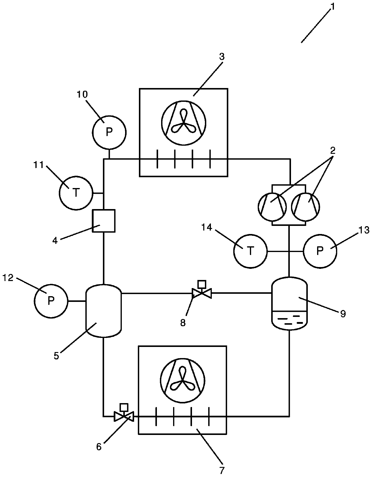
[0048] figure 1 is a simplified diagram of a vapor compression system 1 controlled using a method according to a first embodiment of the invention. A vapor compression system 1 comprises a compressor unit comprising a plurality of compressors 2 (two of which are shown) arranged in a refrigerant path, a heat rejection heat exchanger 3, a high pressure expansion device 4, a receiving 5, an evaporator expansion device 6 in the form of an expansion valve, an evaporator 7, a gas bypass valve 8, and a suction line receiver 9.

[0049] The refrigerant flowing in the refrigerant path is compressed by the compressor 2 before being supplied to the heat rejection heat exchanger 3 . In the heat rejection heat exchanger 3, heat exchange takes place with the auxiliary fluid flow flowing through the heat rejection heat exchanger 3 by removing heat from the refrigerant. In case the heat rejection heat exchanger 3 is in the form of a condenser, the refrigerant passing through the heat reject...


PUM


Abstract

A method for controlling a vapour compression system (1) is disclosed. A mass flow of refrigerant along a part of the refrigerant path is estimated, based on measurements performed by one or more pressure sensors (10, 12, 13) for measuring a refrigerant pressure at selected positions along the refrigerant path and one or more temperature sensors (11, 4) for measuring a refrigerant temperature at selected positions along the refrigerant path. A refrigerant pressure or a refrigerant temperature at a selected position a pressure sensor (10, 12, 13) or temperature sensor (11, 14) along the refrigerant path is derived, based on the estimated mass flow. The vapour compression system (1) is allowed to continue operating, even if a sensor (10, 11, 12, 13, 14) is malfunctioning or unreliable.

Description

technical field [0001] The invention relates to a method for controlling a vapor compression system, such as a refrigeration system, a heat pump or an air conditioning system, wherein the vapor compression system is allowed to keep running in the event of a sensor measuring a control parameter failing. Background technique [0002] Vapor compression systems such as refrigeration systems, heat pumps or air conditioning systems are usually controlled in order to provide the required cooling or heating capacity in the most energy efficient way possible. To this end, a plurality of sensors, such as pressure sensors and temperature sensors, are arranged along the refrigerant path of the vapor compression system, and various components of the vapor compression system, such as valves, compressors, etc. are controlled based on the measurements performed by the sensors. [0003] If one of the sensors fails or is unreliable, the operation of the vapor compression system may become ene...

Claims


Application Information

Patent Timeline
Patent Type & Authority Applications(China)
IPC IPC(8): F25B41/06F25B49/02
CPCF25B41/00F25B49/02F25B2341/0012F25B2400/0407F25B2400/0411F25B2400/075F25B2400/23F25B2500/19F25B2700/13F25B2700/19F25B2700/1933F25B2700/195F25B2700/21F25B2700/21151F25B2700/21163F25B41/34Y02B30/70
Inventor 弗里德·施密特简·普林斯克里斯蒂安·弗里德施隆德肯尼思·班克·马德森
Owner DANFOSS AS
Why Eureka
Try Eureka