Silica gel part forming equipment

A technology for molding equipment and silicone parts, applied in the field of silicone parts molding equipment, can solve the problems of uneven shape of plugging parts, increase of enterprise cost, irregular operation, etc., so as to facilitate later maintenance, increase production rate, and facilitate operation quick effect

Inactive Publication Date: 2019-07-09
SYNERGY HANIL PRECISION POLYMER TECH CO LTD
View PDF0 Cites 0 Cited by
  • Summary
  • Abstract
  • Description
  • Claims
  • Application Information

AI Technical Summary

Problems solved by technology

[0002] Occluders are very common in pipeline applications. There are various types of occluders. Some heavy and clumsy occluders are gradually replaced by light occluders. These light occluders are generally It is made of gel material, so it is very easy to operate, and the improvement in function also makes the application range of the light-duty occluder wider; the silicone parts of the light-duty occluder are basically completed by glue molding process, but due to Different models and specifications of plastic parts will also adopt different glue molding methods. For larger plastic parts, glue injection molding is used, while for some small plastic parts, glue injection molding is used, and fancy structure The plugging silicone parts are basically formed by dispensing. The current dispensing molding needs to be fed through a manual needle tube, and then the amount of glue is manually controlled. The operation is very irregular, and the output of the plugging product is The shape is also uneven, which seriously affects the aesthetics. It also needs secondary processing in the later stage, which is a waste of time and the efficiency is not high. Moreover, this method is also easy to waste raw materials and increase the cost of the enterprise. Therefore, it is urgent to improve the above situation

Method used


Image

  • Silica gel part forming equipment
  • Silica gel part forming equipment

Examples


Embodiment Construction

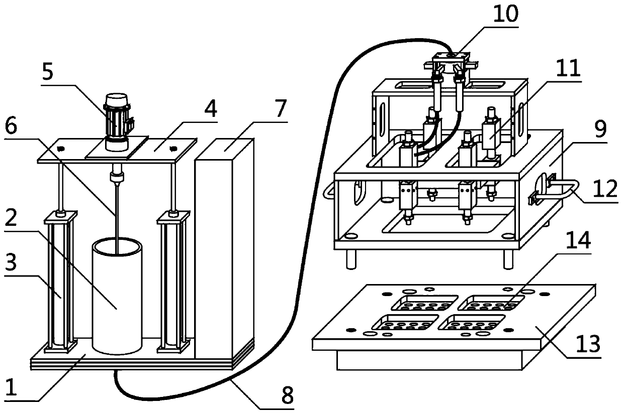
[0019] The specific implementation manners of the present invention will be briefly described below in conjunction with the accompanying drawings.

[0020] Such as figure 1 A molding equipment for silicone parts shown is characterized in that it consists of a frame 1, a barrel 2, two lifting devices 3, a lifting platform 4, an electric control box 7, a glue injection frame 9 and a molding template 13. The cylinder 2 is located on the top of the frame 1, the material cylinder 2 is fixedly connected to the frame 1, and the two lifting devices 3 are respectively located on both sides of the material cylinder 2 in parallel, and the two lifting devices 3 are connected to the frame. 1 is a fixed connection, the lifting platform 4 is located on the top of the two lifting devices 3 and the barrel 2, the lifting platform 4 is fixedly connected with the two lifting devices 3, and the lifting platform 4 is also provided with a stirring drive 5 And stirring rod 6, described stirring driv...


PUM


Abstract

The invention aims to provide silica gel part forming equipment. The technical scheme of the invention is as follows: the silica gel part forming equipment is composed of a rack, a charging barrel, two lifting devices, a lifting platform, an electric control box, a glue injection rack and a forming mold plate. A stirring driver and a stirring rod are arranged on the lifting platform, and a distribution valve, four dispensing valves and two lifting handles are arranged on the glue injection rack. Each dispensing valve is a pneumatic valve, so that the dispensing paces are consistent, the dispensing operation is standardized, the waste of raw materials is avoided, and the production rate is improved. Four forming structural grooves are formed in the forming mold plate, and a pipeline is arranged on the distributing valve. The device is a silica gel forming mechanism which is additionally provided with a storage tank and a mold positioning jig and controls a glue outlet quantity by meansof time to achieve quantitative supply, and saves the material cost to further standardize the operation and improve the production efficiency. The whole device is simple in structure, convenient to operate and environment-friendly and practical. Later maintenance is facilitated according to a split design, so that the expenditure of enterprise cost is reduced.

Description

technical field [0001] The invention relates to the field of mechanical injection molding, in particular to a molding equipment for silicone parts. Background technique [0002] Occluders are very common in pipeline applications. There are various types of occluders. Some heavy and clumsy occluders are gradually replaced by light occluders. These light occluders are generally It is made of gel material, so it is very easy to operate, and the improvement in function also makes the application range of the light-duty occluder wider; the silicone parts of the light-duty occluder are basically completed by glue molding process, but due to Different models and specifications of plastic parts will also adopt different glue molding methods. For larger plastic parts, glue injection molding is used, while for some small plastic parts, glue injection molding is used, and fancy structure The plugging silicone parts are basically formed by dispensing. The current dispensing molding nee...

Claims


Application Information

Patent Timeline
Patent Type & Authority Applications(China)
IPC IPC(8): B29C45/17B29C45/18B29C45/46
CPCB29C45/17B29C45/18B29C45/46
Inventor 魏俊峰鲁晓波
Owner SYNERGY HANIL PRECISION POLYMER TECH CO LTD
Why Eureka
Try Eureka