Head of snow sweeper and automatic snow sweeper

A technology of snowplow and machine head, which is applied in snow surface cleaning, construction, cleaning methods, etc., and can solve problems such as inability to effectively avoid people or objects, damage to people or objects, and occurrence of danger

Active Publication Date: 2019-07-09
POSITEC POWER TOOLS (SUZHOU) CO LTD
View PDF4 Cites 0 Cited by
  • Summary
  • Abstract
  • Description
  • Claims
  • Application Information

AI Technical Summary

Problems solved by technology

[0004] The snowplow is a high-power electric device. The auger on the head rotates at high speed during operation. Whether adults, children, pets, objects, etc., are easily involved in the auger by accident. On the one hand, it is dangerous, on the other hand, it also affects snowplow work
Especially for automatic snowplows, the snowplowing process is generally controlled by intelligent programs, so in the event of an accident, it is impossible to take a timely response strategy and cause serious consequences
Therefore, the defect that the snowplow in the prior art exists is: can not effectively prevent people or things from getting involved in the machine head, thereby easily causing damage to people or things

Method used


Image

  • Head of snow sweeper and automatic snow sweeper
  • Head of snow sweeper and automatic snow sweeper
  • Head of snow sweeper and automatic snow sweeper

Examples


Embodiment 1

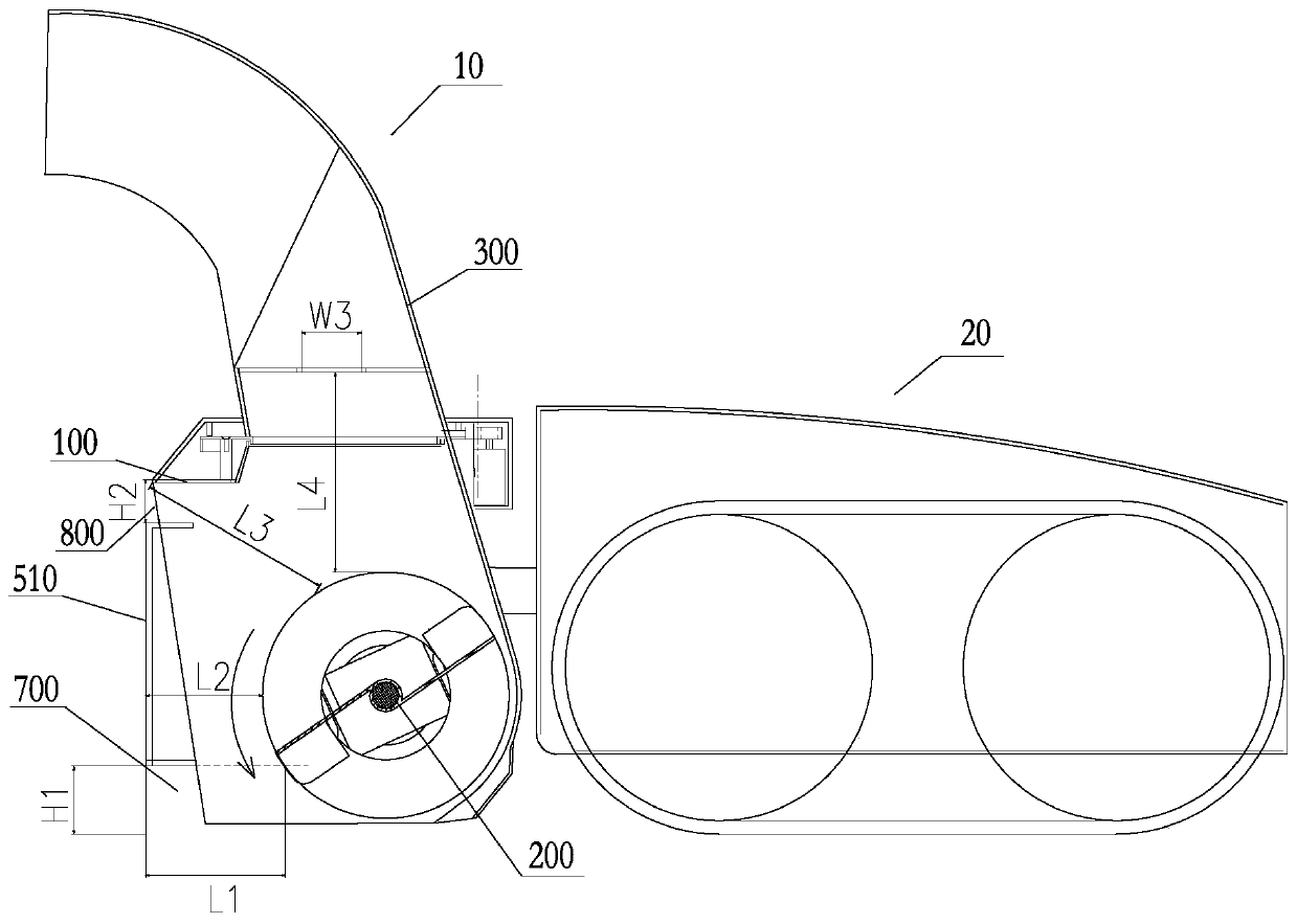
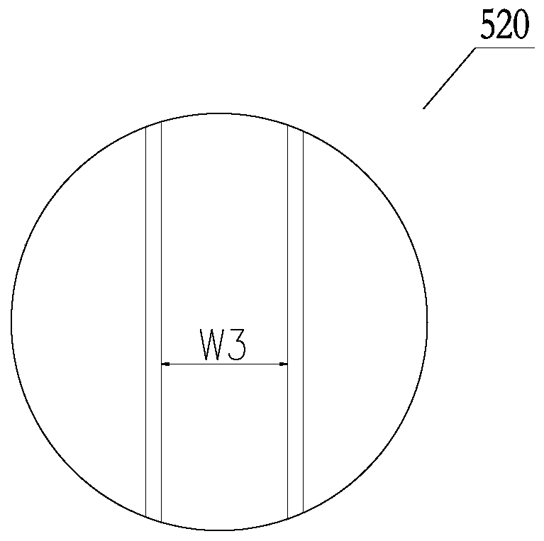
[0072] figure 1 A side view of an embodiment of a snowplow provided by the present invention, wherein the nose of the snowplow is installed on the main machine of the snowplow; figure 2 for figure 1 The partially enlarged schematic diagram of the protective fence of the snow throwing mouth of the snowplow head in .

[0073] Such as figure 1 and figure 2 As shown, the present invention provides a snowplow, which includes a machine head 10 and a main machine 20 , and the machine head 10 includes a guard plate 100 , an auger 200 and a snow blower 300 . The guard plate 100 is formed by a plurality of split plates and surrounds the auger 200 on the top and sides of the auger 200, thereby forming a working chamber for accommodating the auger 200. The working chamber is in front of the auger 200 (the "front" ” refers to the forward direction of the snowplow, such as figure 1 The left side of the center) is formed with a snow inlet to receive the snow to be cleared. The snow b...

Embodiment 2

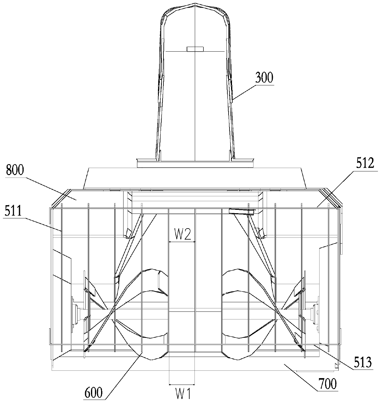
[0118] image 3 The front view of another embodiment of the snowplow provided by the present invention shows that the lower auxiliary protective rib is installed at the bottom of the snow inlet protective fence.

[0119] In this embodiment, the lower fixing ribs 513 are connected to the lower ends of the snow inlet protective ribs 511, that is, the snow inlet protective ribs 511 end at the lower fixing ribs 513, and the lower auxiliary protective ribs 600 continue to extend downward from the lower fixing ribs 513. out.

[0120] In this way, a protective structure is added at the bottom of the snow inlet protective fence 510, and the lower auxiliary protective rib 600 prevents the adult's hands, feet, children's arms, etc. The downward protruding of the fixing ribs 513 is also beneficial to cutting the snow accumulation and relieving the resistance of the snow accumulation.

[0121] The lower auxiliary protective ribs 600 are arranged parallel to each other, and the maximum d...

Embodiment 3

[0131] Figure 4 and Figure 5 A schematic diagram of another snowplow 10 provided by the present invention is shown. This other snowplow 10 does not have a snow throwing barrel, and the snow processed by the auger is directly thrown from the tangential direction of the auger rotation direction. The snow inlet protective fence with the same structure as the above-mentioned snowplow 10 can be used.

[0132] In this embodiment, there is no gap in the up and down direction between the snow inlet protective fence 510 and the top of the guard plate, the snow inlet protective fence directly extends to the top of the guard plate, and the snow inlet protective fence 510 and the bottom of the guard plate There is a gap in the up and down direction.

[0133] It should be understood that in other variations of Embodiment 1 and Embodiment 2, there may also be an upper auxiliary protective rib protruding upward from the snow inlet protective fence 510, and in other variations of Embodime...


PUM


Abstract

The invention discloses a head of a snow sweeper and an automatic snow sweeper. The head of the snow sweeper comprises a guard plate and an auger, wherein the guard plate forms a working chamber for containing the auger, the working chamber is provided with a snow inlet of which the opening faces the traveling direction of the snow sweeper, and a snow inlet protective fence located in front of theauger and fixed to the guard plate is arranged at the snow inlet. When the snow sweeper performs snow sweeping operation, in the case that hands and feet of people, pets, sundries and the like whichare accidentally mixed in to-be-cleaned accumulated snow are about to enter the auger, the snow inlet protective fence can block the hands and feet of people, the pets, the sundries and the like fromthe working chamber, so that conscious people can retract their hands and feet in time, the pets can run away in time, and the sundries can be pushed away by the snow inlet protective fence to be taken away in time, thereby avoiding danger and the influence on the snow sweeping work.

Description

technical field [0001] The invention relates to an automatic snow plowing device, in particular to a head of a snow plow and an automatic snow plow including the head. Background technique [0002] Snow plows are important equipment for snow removal in winter. A snowplow generally includes a main engine and a head, and the main engine is the main body of the snowplow and is used to push the snowplow forward. The machine head generally includes a guard plate and a spiral auger, the guard plate forms a working chamber, and the auger is accommodated in the working chamber to break up the snow blocks to be thrown out. [0003] According to the snow throwing method, the snow blower is also divided into the snow blower type and the direct throwing type. The snow blower type snow blower is equipped with a snow blower on the top of the machine head, which is used to throw the snow scattered by the auger. The direct-throwing snowplow does not have such a snow blower, but directly t...

Claims


Application Information

Patent Timeline
Patent Type & Authority Applications(China)
IPC IPC(8): E01H5/09
CPCE01H5/09E01H5/098
Inventor 赵凤丽查霞红
Owner POSITEC POWER TOOLS (SUZHOU) CO LTD
Why Eureka
Try Eureka