
Oven fan system

A fan system and oven technology, applied in the field of ovens, can solve the problem that the effect of double fans being placed vertically up and down is not optimal, and achieve the best baking effect.

Pending Publication Date: 2019-07-09
NINGBO FOTILE KITCHEN WARE CO LTD
View PDF0 Cites 0 Cited by
  • Summary
  • Abstract
  • Description
  • Claims
  • Application Information

AI Technical Summary

Problems solved by technology

However, in the case that the inner liner of the oven is not layered, in some baking modes, the effect of placing the double fans vertically up and down is not optimal

Method used


Image

  • Oven fan system
  • Oven fan system
  • Oven fan system

Examples


Embodiment Construction

[0019] The present invention will be further described in detail below in conjunction with the accompanying drawings and embodiments.

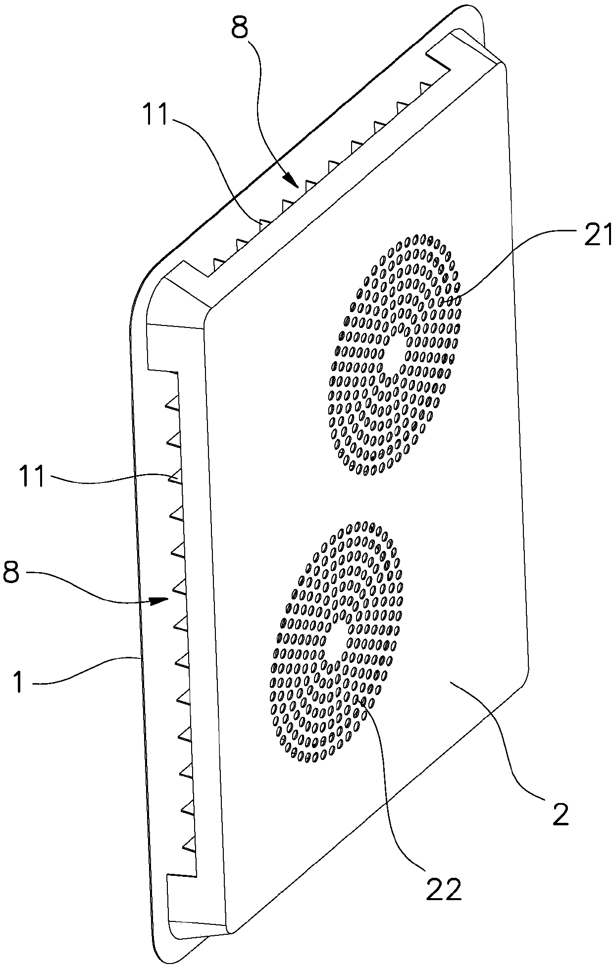
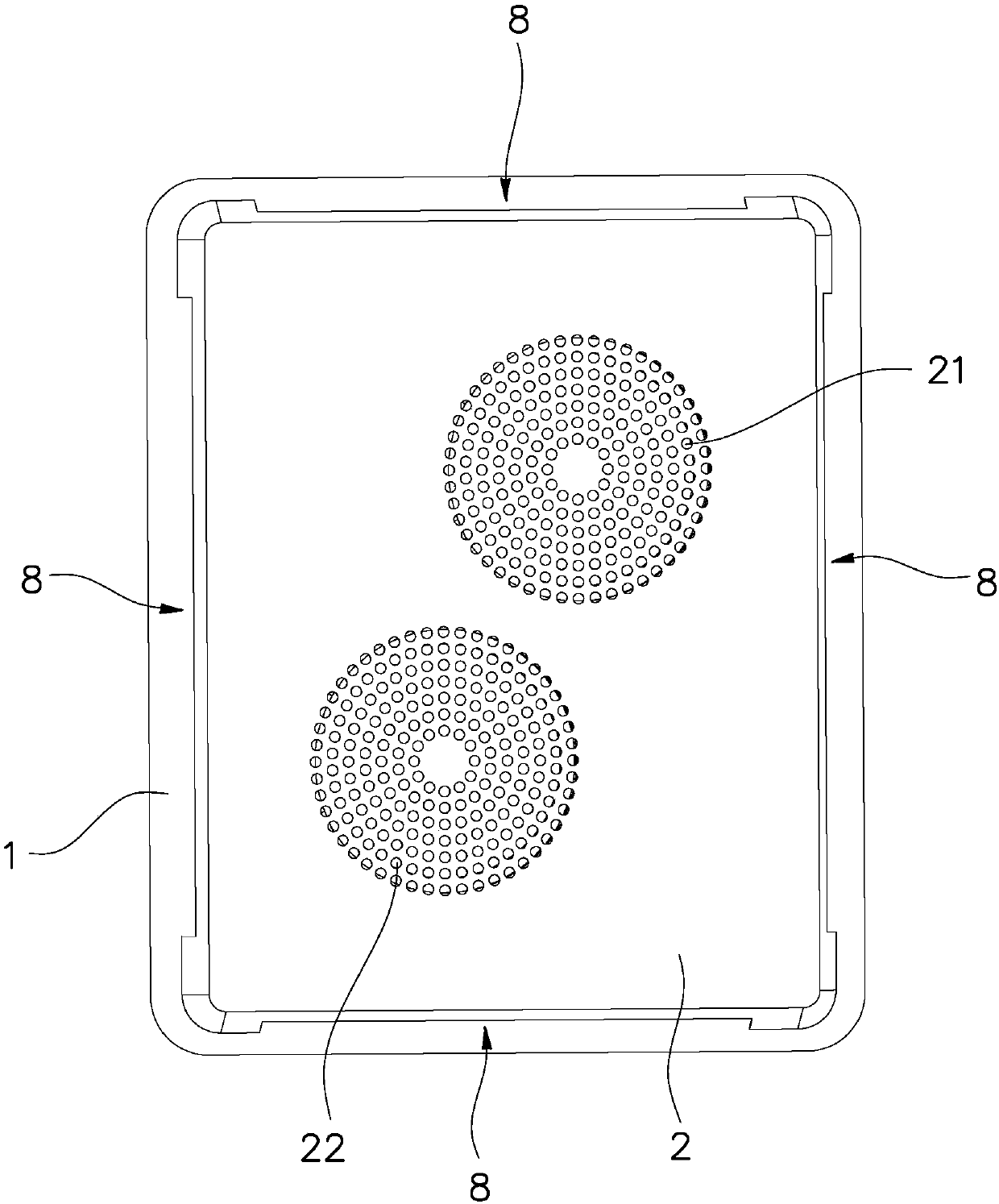
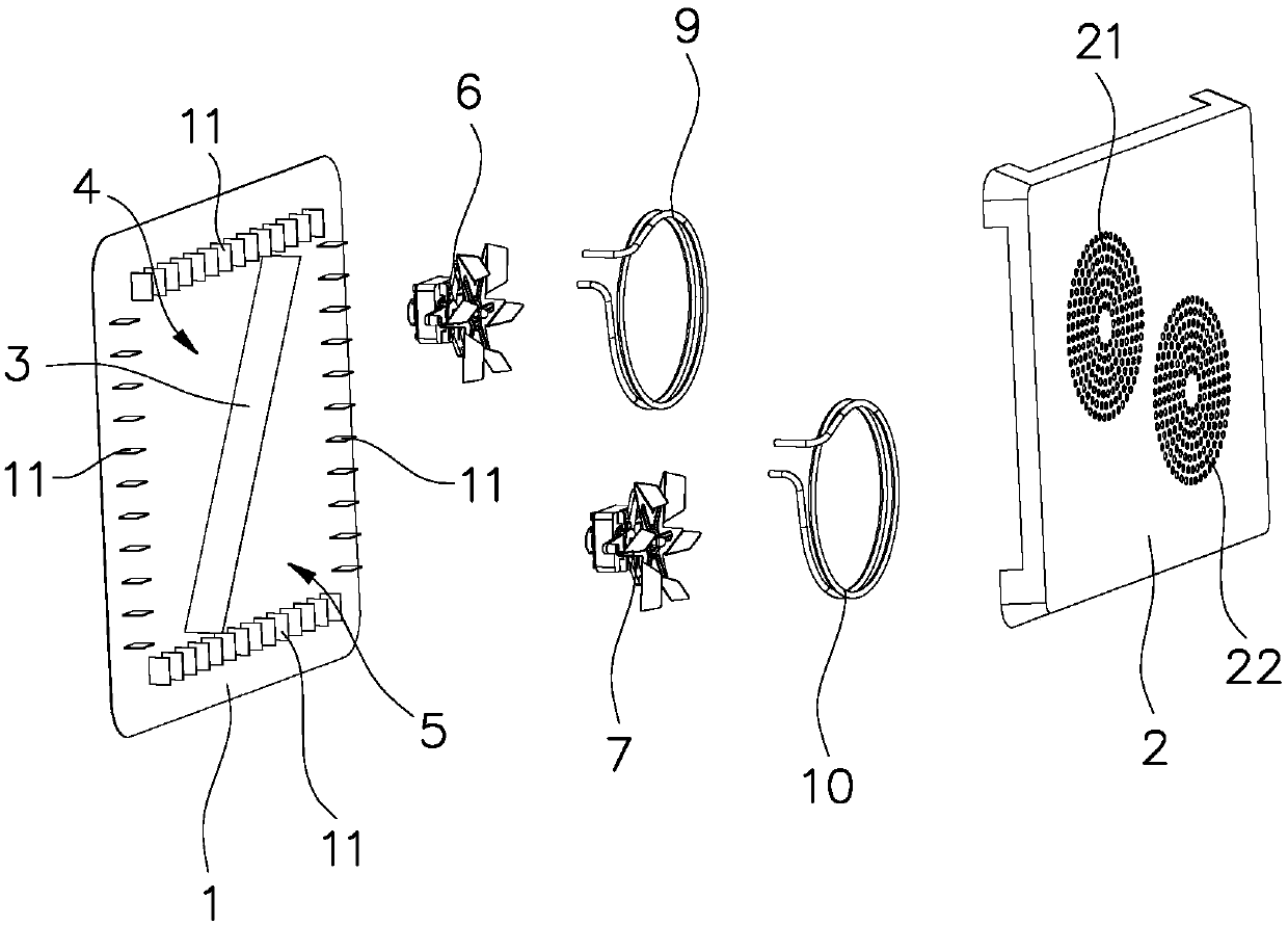
[0020] Such as Figure 1 to Figure 4 As shown, the hot air baffle of the oven fan system in this embodiment includes a first baffle 1 and a second baffle 2, a hot air chamber is formed between the first baffle 1 and the second baffle 2, and the inside of the hot air chamber passes The baffle 3 is divided into a first hot air chamber 4 and a second hot air chamber 5 with the same volume. The plate 1 and the second baffle plate 2 are generally square, therefore, the first hot air chamber 4 and the second hot air chamber 5 are generally triangular.

[0021] Hot air blower comprises the same first hot air blower 6 and the second hot air blower 7 of power, and the first hot air blower 6 is installed and the first heating pipe 9 is in the first hot blast chamber 4, and the first hot air chamber 4 of the impeller of the first hot air blower 6 Insid...


PUM


Abstract

An oven fan system comprises a hot-air blower baffle, a hot-air blower and a heating pipe; the hot-air blower baffle comprises a first baffle and a second baffle; a hot air chamber is formed between the first baffle and the second baffle; the interior of the hot air chamber is divided into a first hot air chamber and a second hot air chamber through a partition plate obliquely arranged relative tothe horizontal plane. The hot-air blower comprise a first air heater mounted in the first hot air chamber and a second air heater mounted in the second hot air chamber; a first hot air backflow opening corresponding to the first air heater and a second hot air backflow opening corresponding to the second air heater are formed in the second baffle, and hot air outlets are formed in the periphery of the first baffle and the periphery of the second baffle. According to the oven fan system, the hot air chamber is divided into the first hot air chamber and the second hot air chamber through the obliquely arranged partition plate; the first air heater and the second air heater are asymmetrically arranged up and down, so that the performance of the double air heaters of the oven can be optimallyexerted in some modes, and an optimal baking effect can be achieved under the condition that an inner container of the oven is not layered.

Description

technical field [0001] The invention relates to the field of ovens, in particular to an oven fan system. Background technique [0002] In the heater system of the oven, the heater mainly blows the air heated by the heating tube out from the air outlet of the heater baffle. It can be seen that the position of the oven heater has a great influence on the internal circulation in the oven liner. The position of the hot air blower in the oven liner is different, and the oven will have different baking effects. At present, the ovens on the market are mainly single fan, and the hot air fan is generally placed in the middle of the back of the oven, which can maximize the circulation of hot air in the oven liner and ensure the uniformity and efficiency of the oven temperature field. If the dual fan structure is considered, the two hot air fans placed up and down are relatively simple in structure, and the upper and lower layered baking functions of the oven can also be realized. H...

Claims


Application Information

Patent Timeline
IPC IPC(8): F26B21/00A47J37/06
CPCF26B21/001A47J37/0754
Inventor 杨均王黎喆曹骥
Owner NINGBO FOTILE KITCHEN WARE CO LTD
Learn More