
A gcs type low voltage withdrawable switchgear

A low-voltage withdrawable switchgear technology, applied in the field of switchgear, can solve the problems of personnel and components safety cannot be guaranteed, live operation and other problems, achieve the effect of ingenious structure, avoid live operation, and ensure safety

Active Publication Date: 2020-05-22
星凯电气有限公司
View PDF8 Cites 0 Cited by
  • Summary
  • Abstract
  • Description
  • Claims
  • Application Information

AI Technical Summary

Problems solved by technology

[0006] In view of the above situation, in order to overcome the defects of the prior art, the present invention provides a GCS type low-voltage withdrawable switchgear, which effectively solves the problem of misoperation such as live operation in the drawer of the existing switchgear, and the safety of personnel and components. non-guaranteed issues

Method used


Image

  • A gcs type low voltage withdrawable switchgear
  • A gcs type low voltage withdrawable switchgear
  • A gcs type low voltage withdrawable switchgear

Examples


Embodiment Construction

[0019] The specific implementation manners of the present invention will be further described in detail below in conjunction with the accompanying drawings.

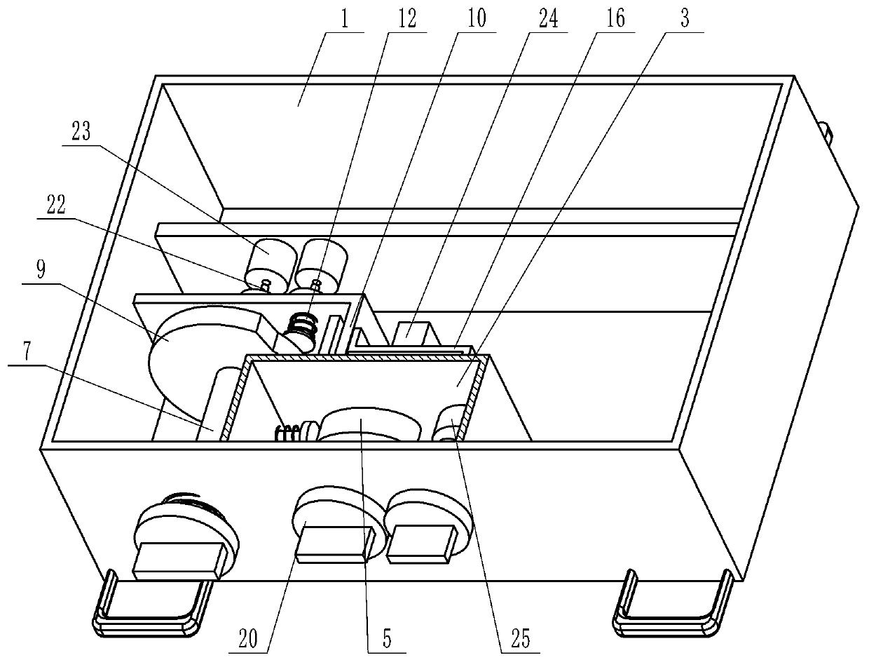
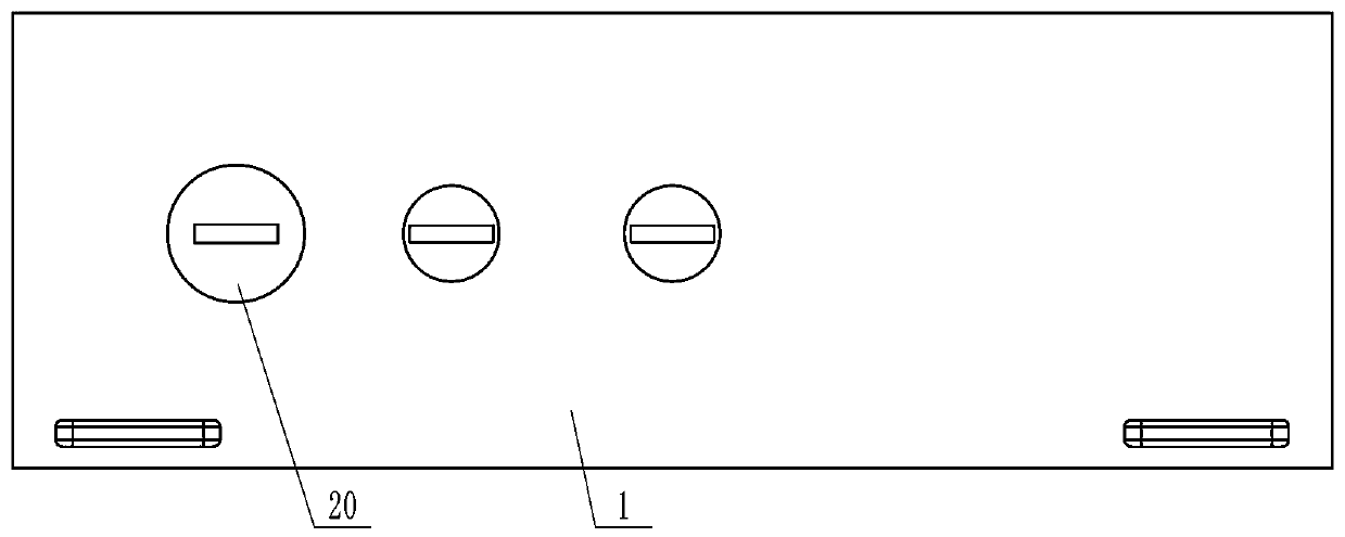
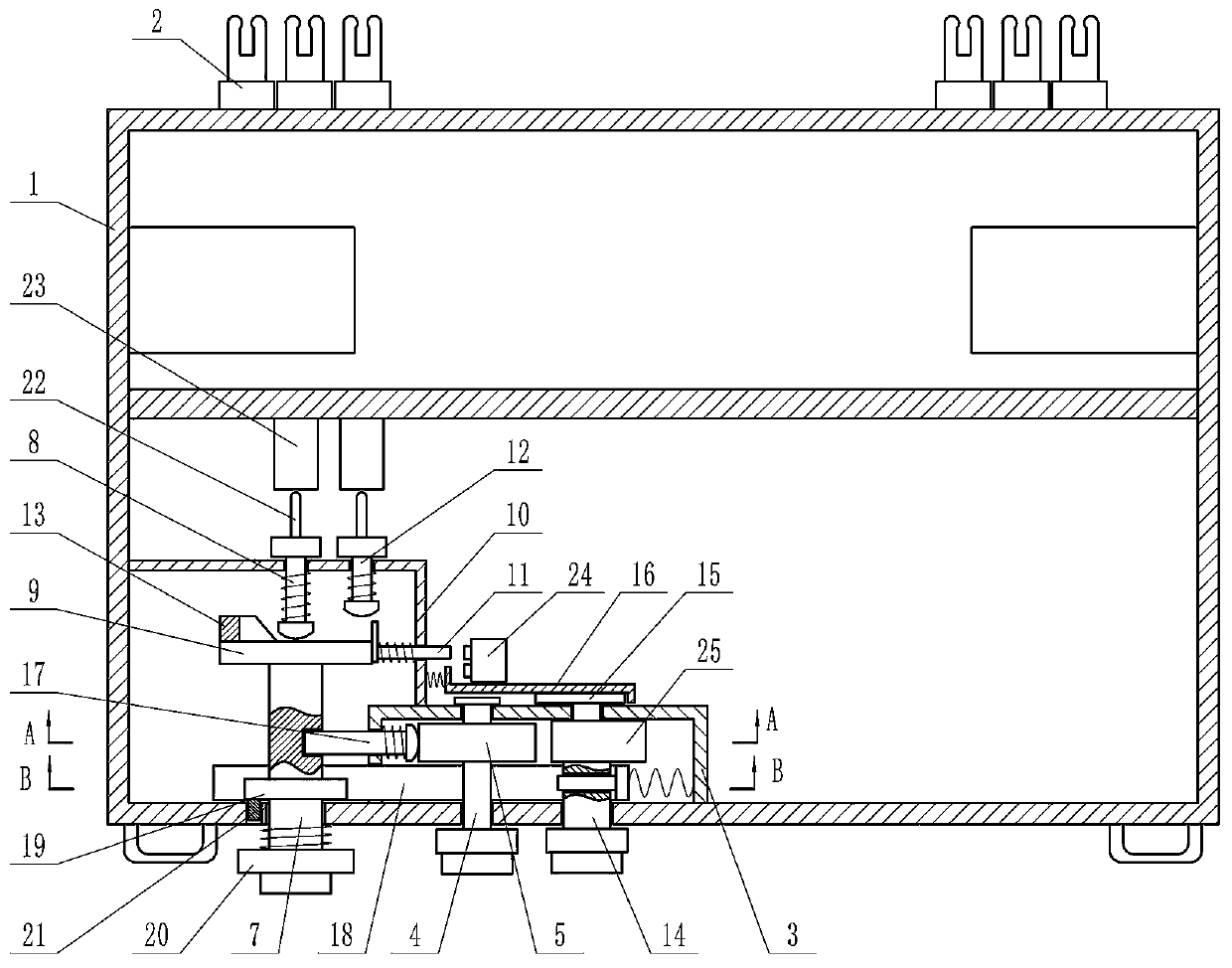
[0020] Depend on Figure 1 to Figure 10 Given, the present invention comprises switchgear cabinet body, and a plurality of drawers 1 are arranged in the cabinet body, and the plug 2 that is connected with the cabinet body is arranged on the rear side of drawer 1, and rectangular housing 3 is fixed on the inner side of drawer 1 front side plate, and housing 3 There is a first rotating shaft 4 arranged along the front and rear directions inside, the front end of the first rotating shaft 4 runs through the front side panel of the drawer 1 and is placed in front of the drawer 1, the first rotating shaft 4 has an oval first cam 5, and the upper and lower sides of the housing 3 A vertical movable plate 6 that can move up and down runs through the board, and one end of the movable plate 6 keeps in contact with the first cam 5, ...


PUM


Abstract

The invention provides a GCS low-voltage draw-out switch cabinet. The problem that the drawers of the existing switch cabinet are prone to incorrect operation such as live operation and the safety ofpersonnel and components cannot be guaranteed is solved. The technical scheme adopted to solve the problem is as follows: the switch cabinet comprises a switch cabinet body which is internally provided with multiple drawers, a shell is fixed on the inner side of the front side plate of the drawers, a first rotating shaft is arranged in the shell, a first cam is arranged on the first rotating shaft, and movable plates run through the upper and lower side plates of the shell respectively; a second rotating shaft is arranged on the left side of the shell, and a first ejector rod is arranged at the back of the second rotating shaft; a second cam is fixed at the back end of the second rotating shaft, a longitudinal plate is fixed at the back of the shell, and a cross rod runs through the longitudinal plate; a second ejector rod is arranged on the right side of the first ejector rod, and a wedge block is arranged on the back end face of the second cam; and a third rotating shaft is arrangedon the right side of the first rotating shaft, the back end of the third rotating shaft runs through the back side plate of the shell, a third cam is arranged at the back end of the first rotating shaft, and a pull plate capable of moving from side to side is arranged on the third cam.

Description

technical field [0001] The invention relates to the technical field of switch cabinets, in particular to a GCS type low-voltage withdrawable switch cabinet. Background technique [0002] GCS type AC low-voltage switchgear is a low-voltage power distribution cabinet designed in line with the principles of safety, economy, rationality and reliability. Low-voltage switchgear is suitable for power plants, petroleum, chemical industry, metallurgy, textiles, high-rise buildings and other industries, as power transmission, For power distribution and power conversion. [0003] The drawer in the GCS type AC low-voltage switchgear is divided into five states, as follows: 1. The "extraction position" is the primary and secondary circuits are disconnected from the main circuit, the drawer and the cabinet are interlocked to open, and the drawer can be pushed forward , Extraction operation; 2. "Isolation position" means that the primary and secondary circuits are disconnected from the ma...

Claims


Application Information

Patent Timeline
Patent Type & Authority Patents(China)
IPC IPC(8): H02B11/133
CPCH02B11/133
Inventor 史运周张素平
Owner 星凯电气有限公司
Learn More