Locking and releasing device

A locking release and locking device technology, which is applied in transportation and packaging, lighter-than-air aircraft, balloon aircraft, etc., can solve the problems of operator safety hazards, affecting detection performance, and complex design, etc., to achieve simple operation and structure The effect of low complexity and improved applicability

Active Publication Date: 2019-07-12
CHINA ELECTRONIC TECH GRP CORP NO 38 RES INST
View PDF7 Cites 3 Cited by
  • Summary
  • Abstract
  • Description
  • Claims
  • Application Information

AI Technical Summary

Problems solved by technology

[0003] Before the tethered balloon is inflated, the capsule body is fixed on the installation frame. Generally, the balloon is released by manual unlocking at the moment the capsule is filled with gas to form a balloon. Due to the fast inflation speed of the balloon, this release method is likely to cause safety hazards for operators. At the same time The uneven force of manual unlocking will easily cause the electronic equipment mounted on the tethered balloon to shake and vibrate, which will affect the detection performance
However, the design of the existing automatic unlocking device is relatively complicated, and it is not suitable for the release of the tethered balloon capsule 5 during the inflation process, and it is also prone to malfunctions such as jamming in harsh environments

Method used


Image

  • Locking and releasing device
  • Locking and releasing device
  • Locking and releasing device

Examples


Embodiment 1

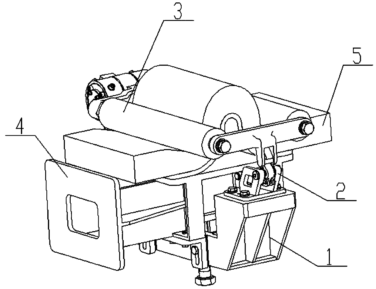
[0029] Such as figure 1 as shown, figure 1 It is a structural diagram of the locking release device of the present invention; the locking release device of the present invention includes a base 1, a locking device 2, and a pressing device 3, and the pressing device 3 includes a fixed end and a movable end, so The fixed end is movably connected with the base 1 , and the movable end can be connected with the base 1 through the locking device 2 . When both ends of the pressing device 3 are connected to the base 1 at the same time, a placement cavity is formed between the pressing device 3 and the base 1, and the tethered balloon body 5 can be placed on the base. Place it in the cavity, and lock and fix the corresponding part of the captive balloon body 5 through the pressing device 3 and the base 1 .

[0030] Preferably, the base 1 is arranged as a U-shaped structure, and the pressing device 3 is arranged at the open end of the base 1, so that the pressing device 3 and the base...

Embodiment 2

[0045] The locking release device also includes a fixing device 4, the fixing device 4 is arranged in the placement cavity, and the fixing device 4 strengthens the locking and fixing effect on the tethered balloon body 5 in the locked state .

[0046] Such as Figure 8 as shown, Figure 8 It is a structural view of the fixing device; the fixing device 4 includes a base 41 and an extruding part 42, the extruding part 42 is fixedly arranged on the upper part of the base 41, and the extruding part 42 passes through the base 41 and the extruding part 42. The base 1 is connected, and the base 41 is used to improve the stability of the structure and position of the extrusion part 42 .

[0047] Preferably, the extruded part 42 is arranged as a protrusion with a symmetrical structure, that is, from the extension direction of the extruded part 42 from both sides to the middle, the height dimension of the extruded part 42 gradually becomes larger, so that in the The middle position o...

Embodiment 3

[0053] The quick release device of the present invention is mainly used on the flying device when the moored gas is released. The flying device generally includes a flying frame, and the quick releasing device is arranged on the flying frame. The release device fixes the tethered balloon body 5 on the flying frame in the horizontal state, and adjusts the flying frame to an inclined or vertical state, and then inflates the tethered balloon body 5 During the process, the tethered balloon capsule 5 is released instantaneously, thereby realizing the release of the tethered balloon.

[0054] Preferably, more than three quick release devices are provided on the flying frame at the same time, so as to ensure the fixing effect of the flying frame on the captive balloon body 5 . Since the tethered balloon body 5 itself has a certain gravity, and is also accompanied by other equipment, through the structural setting of the quick release device, it is avoided that the flying frame is adj...


PUM


Abstract

The invention discloses a locking and releasing device, which comprises a base, a locking device and a compressing device. The compressing device comprises a fixed end and a movable end, the fixed endis movably connected with the base, and the movable end is connected with the base through the locking device; and a placement cavity is formed between the compressing device and the base, and a tethered balloon bag body can be placed in the placement cavity, and is locked and fixed through the compressing device and the base. Through structural arrangement of the locking device, the compressingdevice can be pressed downwards and locked, and automatically released simultaneously, and the locking and releasing device is low in structure complexity degree and easy to operate.

Description

technical field [0001] The invention relates to the field of tethered balloon equipment, in particular to a locking release device. Background technique [0002] As a kind of floating platform, the tethered balloon can be suspended in the troposphere and stratosphere. It has a wide range of application prospects in both military and civilian applications. Due to its flexibility, it is especially suitable for carrying electronic equipment such as search and reconnaissance and communication interference. [0003] Before the tethered balloon is inflated, the capsule body is fixed on the installation frame. Generally, the balloon is released by manual unlocking at the moment the capsule is filled with gas to form a balloon. Due to the fast inflation speed of the balloon, this release method is likely to cause safety hazards for operators. At the same time The uneven force of manual unlocking can easily cause the electronic equipment mounted on the tethered balloon to shake and v...

Claims


Application Information

Patent Timeline
Patent Type & Authority Applications(China)
IPC IPC(8): B64B1/50B64B1/66
CPCB64B1/50B64B1/66
Inventor 王虎邱坤滨张增太何文杰彭伟吴影生
Owner CHINA ELECTRONIC TECH GRP CORP NO 38 RES INST
Why Eureka
Try Eureka