Vacuum sweeper truck bed and vacuum sweeper

A technology for vacuuming vehicles and carriages, which is applied in the field of sanitation vehicles. It can solve the problems of low utilization rate of filtration area, short continuous operation cycle, and influence on work efficiency, and achieve simple and efficient installation and maintenance, long continuous working time, and high filter element utilization. high effect

Pending Publication Date: 2019-07-12
奥力武汉汽车有限公司
View PDF0 Cites 0 Cited by
  • Summary
  • Abstract
  • Description
  • Claims
  • Application Information

AI Technical Summary

Problems solved by technology

At present, there are problems in the actual operation of the vacuum truck: due to the continuous operation of the vacuum truck, the dust moves continuously with the air flow, which causes the filter device to be overloaded and the dust removal is too difficult, and the parts of the filter device of the dust collector become wearing parts, while Dust collectors are

Method used


Image

  • Vacuum sweeper truck bed and vacuum sweeper
  • Vacuum sweeper truck bed and vacuum sweeper
  • Vacuum sweeper truck bed and vacuum sweeper

Examples


Embodiment 1

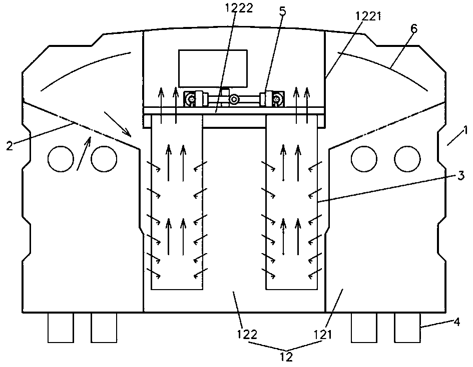
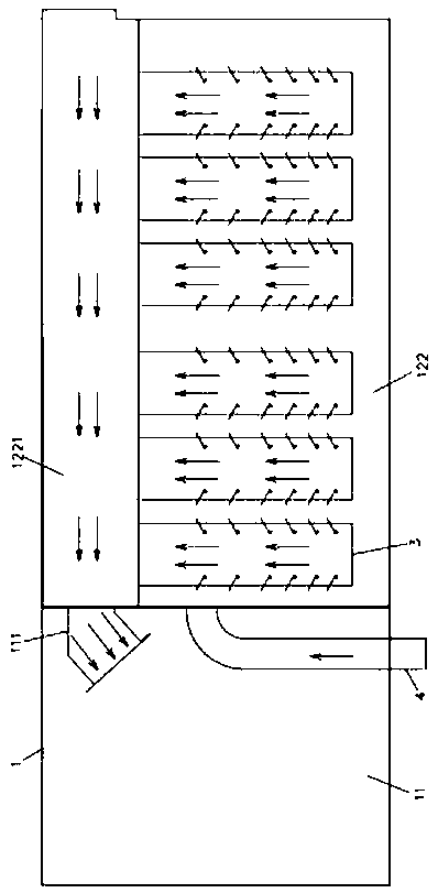
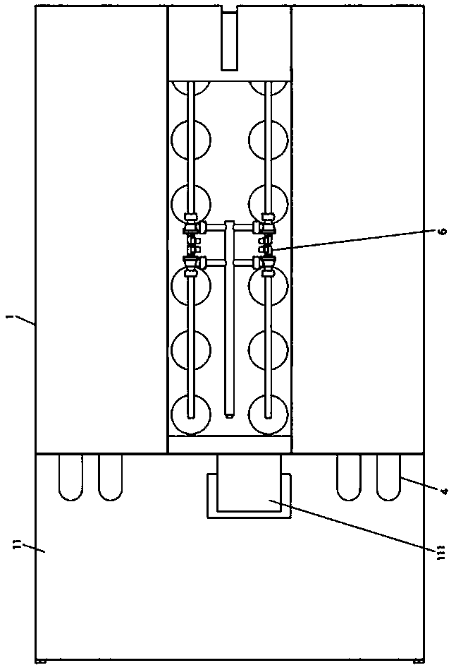
[0032] Embodiment one: if Figures 1 to 3 As shown, the dust collection vehicle compartment of this embodiment includes a box body 1, the box body 1 is a cuboid shape arranged horizontally along the front and rear directions, and its interior is provided with mutually independent air outlet bins 11 and dust removal bins 12 along the front and rear directions. At least one side of the left and right direction inside the dust removal chamber 12 is provided with an air inlet chamber 121, and the remaining part forms a filter chamber 122. An air duct 1221 extending to the front and rear ends is provided along the front and rear direction, and the air outlet 111 communicating with the air duct 1221 is provided inside the above-mentioned air outlet bin 11; the coarse-effect filter device 2, the above-mentioned coarse-effect filter device 2 is detachable The above-mentioned air hole is installed at the above-mentioned air hole; the filter element 3, the above-mentioned filter element...

Embodiment 2

[0050] Embodiment 2: This embodiment provides a dust collection truck compartment, including the dust collection truck compartment in Embodiment 1. During the assembly process, the power supply of the electrical components inside the compartment is connected to the vehicle power supply of the entire dust collection truck, and involves The control circuit or controller of the electronically controlled device is installed in the cab of the vacuum cleaner, which is convenient for the driver to operate with one button.


PUM


Abstract

The invention relates to the technical field of sanitation vehicles, in particular to a vacuum sweeper truck bed and a vacuum sweeper. The vacuum sweeper truck bed comprises a box body, a coarse filter device, a plurality of filter elements and air inlet pipes, an air outlet bin and a dust removal bin are arranged in the box body in the front and rear directions, air inlet chambers are formed in at least one side of the interior of the dust removal bin in the left and right directions, a filter chamber is formed in the other parts, air holes are formed in the upper parts of the air inlet chambers, an air dust is arranged on the top wall of the filter chamber, and an air outlet communicating with the air duct is formed in the air outlet bin; the coarse filter device is mounted at the air holes; the filter elements are barrels with open upper ends and separately and vertically distributed in the dust removal bin at intervals in the front and rear directions, the upper ends of the filterelements separately penetrate through the bottom wall of the air duct and communicate with the interior of the air duct, and the lower ends of the filter elements extend downwards and are close to thebottom of the dust removal bin; and one ends of the air inlet pipes communicate with the interiors of the air inlet chambers, and the other ends of the air inlet pipes form an air inlet. The vacuum sweeper truck bed has the advantages that air flow can be filtered without dead angles in the working process, the utilization rate of the filter elements is higher, continuous working time is long, and installation and maintenance are simple and efficient.

Description

technical field [0001] The invention relates to the technical field of sanitation vehicles, in particular to a dust collection vehicle box and a dust collection vehicle. Background technique [0002] Vacuum trucks are widely used for cleaning roads, squares, docks, airports, cement factories, coal mines, power plants and other places. They use airflow to complete the work, and use airflow to collect garbage and dust. It has the characteristics of small amount and no water operation, especially suitable for dry and rainless areas such as the west and north. At present, there are problems in the actual operation of the vacuum truck: due to the continuous operation of the vacuum truck, the dust moves continuously with the air flow, which causes the filter device to be overloaded and the dust removal is too difficult, and the parts of the filter device of the dust collector become wearing parts, while Dust collectors are generally installed on the top of the carriage and placed...

Claims


Application Information

Patent Timeline
IPC IPC(8): E01H1/08
CPCE01H1/0836
Inventor 肖俊曾萌黄松师徐俊
Owner 奥力武汉汽车有限公司
Why Eureka
Try Eureka