Sliding type gear shifter

A shifter, sliding technology, applied in transmission control, components with teeth, belts/chains/gears, etc., can solve the problems of high cost, false induction, etc., and achieve low cost, good hand feeling, and reliable guarantee sexual effect

Pending Publication Date: 2019-07-12
宁波鹏程汽车系统有限公司
View PDF0 Cites 4 Cited by
  • Summary
  • Abstract
  • Description
  • Claims
  • Application Information

AI Technical Summary

Problems solved by technology

[0003] In the prior art, most of the shift levers of the electronic shifters are rotary, but because the existing technology needs to greatly reduce the space of the shifter, the internal structure design of the shifter is required to be extremely compact, which leads to the rotary The magnet and Hall sensing areas in the shifter are too compact, so there will be a problem of false sensing. The existing solutions on the market are:
[0004] 1. Adopt the induction method that can use a single three-axis Hall, but because the three-axis Hall is more than 30 times more expensive than the ordinary switch Hall, it leads to higher costs;
[0005] 2. Using the induction method of one side multilevel magnet and Hall matrix, one side multilevel magnet is more than 10 times more expensive than ordinary ferrite magnets, so it will also lead to higher costs

Method used


Image

  • Sliding type gear shifter
  • Sliding type gear shifter
  • Sliding type gear shifter

Examples


Embodiment Construction

[0028] The present invention will be further described below through specific embodiments, but the present invention is not limited to the following specific embodiments.

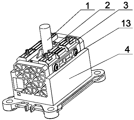
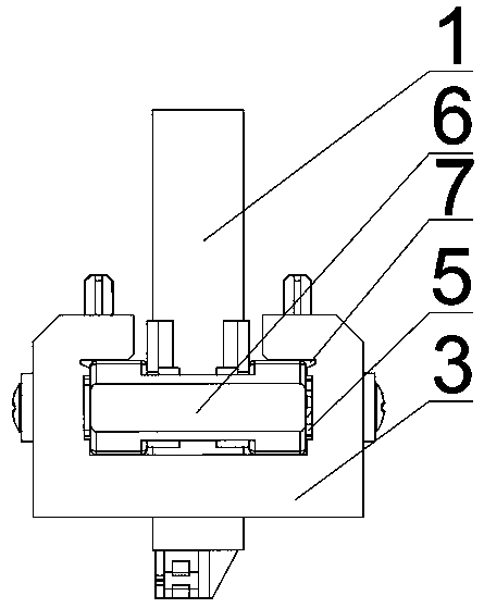
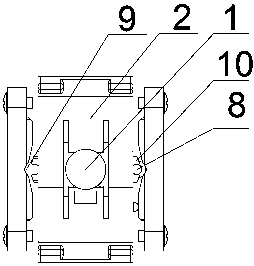
[0029] A sliding shifter, comprising a shift lever 1, a slider 2, a slide seat 3 and a shifter seat 4, the slide seat 3 is fixed on the shifter seat 4, and the shift lever 1 is fixed on On the slider 2, and the slider 3 is provided with a chute 5, the slider 2 is slidingly fitted on the chute 5, the shifter seat 4 is provided with a control circuit board, and the control circuit board is provided with a Hall Inductive element, in this specific embodiment, Hall inductive element is common switch Hall, and cost is relatively low, is provided with magnetic piece at the bottom of shift lever 1, as Figure 6 As shown, it is a comparison diagram of the prior art rotary shifter and the sliding shifter of the present application. It can be clearly seen from the figure that the distance between each Hall sensing ele...


PUM


Abstract

The invention relates to the technical field of gear shifters, in particular to a sliding type gear shifter. The sliding type gear shifter comprises a gear shifting rod (1), a sliding block (2), a sliding base (3) and a gear shifter base (4). The sliding base (3) is fixed to the gear shifter base (4). The gear shifting rod (1) is fixed to the sliding block (2). The sliding base (3) is provided with a sliding groove (5). The sliding block (2) is in sliding fit in the sliding groove (5). The gear shifter is low in cost and high in reliability.

Description

technical field [0001] The invention relates to the technical field of shifters, in particular to a sliding shifter. Background technique [0002] Compared with the traditional shifter, the electronic shifter has great advantages: the electronic shifter does not have a cable structure, so it occupies less space in the central aisle, and the OEM can greatly increase the storage space on the central aisle; The shifter uses a large number of electrical signal transmissions, so it can achieve better appearance and lighting effects; the electronic shifter cancels the hard connection with the gearbox through the cable, and the force at the gearbox end will not affect the gear shift through the cable The shifting feel of the shifter improves the quality of the shifting operation; so the electronic shifter in the prior art is widely used. [0003] In the prior art, most of the shift levers of the electronic shifters are rotary, but because the existing technology needs to greatly r...

Claims


Application Information

Patent Timeline
Patent Type & Authority Applications(China)
IPC IPC(8): F16H59/02
CPCF16H59/02
Inventor 吴学超
Owner 宁波鹏程汽车系统有限公司
Why Eureka
Try Eureka