Mobile robot and return charging method
A mobile robot and charging method technology, applied in the direction of secondary battery charging/discharging, circuit, manipulator, etc., can solve the problem of wrong route navigation, unable to complete charging normally, unable to directly connect with ultrasonic signals, etc., to achieve the effect of improving the success rate
- Summary
- Abstract
- Description
- Claims
- Application Information
AI Technical Summary
Problems solved by technology
Method used
Image

Examples
Embodiment 1
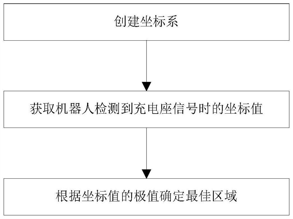
[0033] Such as Figure 7 As shown, in order to facilitate the description of specific implementation methods, in this embodiment, the signal emitted by the charging stand is an infrared signal and the infrared emission angle of the charging stand is less than 90°, and the mobile robot traverses the infrared signal coverage area during operation. With the charging stand as the origin 0, the Y axis is perpendicular to the front of the charging stand, and the X axis is parallel to the front of the charging stand to establish a plane Cartesian coordinate system xOy. In this embodiment, Y min →0, at this time Y max -Y min >X max -X min , the reason is that the infrared signal emission angle θ≤90°, at this time the maximum extension width L perpendicular to the front direction of the charging stand will be greater than / equal to the maximum extension width W parallel to the front direction of the charging stand, where W=2*L*sinθ , that is, L≥W when θ≤90°. The calculation method ...
Embodiment 2
[0042] Such as Figure 9 As shown, in order to facilitate the description of specific implementation methods, in this embodiment, the signal emitted by the charging stand is an infrared signal and the infrared emission angle of the charging stand is less than 90°, and the mobile robot traverses the infrared signal coverage area during operation. Taking the charging stand as the origin 0, the Y axis perpendicular to the front of the charging stand, and the X axis parallel to the front of the charging stand to establish a plane Cartesian coordinate system xOy, in this embodiment X min →0, at this time Y max -Y min max -X min The calculation method provided by the present invention can determine the coefficients m and n of the optimal area P as follows: n is 1, and m is between 1 / 3 and 2 / 3.
[0043] When m=1 / 3, P(x)=X min +1 / 3*(X max -X min )≈1 / 3*X max , P(y)=(Y max +Y min ) / 2; at this time, according to the attached Figure 8 A limit suitable point for determining the ...
PUM
 Abstract
Description
Claims
Application Information
 - R&D
- Intellectual Property
- Life Sciences
- Materials
- Tech Scout
- Unparalleled Data Quality
- Higher Quality Content
- 60% Fewer Hallucinations
Browse by: Latest US Patents, China's latest patents, Technical Efficacy Thesaurus, Application Domain, Technology Topic, Popular Technical Reports.
© 2025 PatSnap. All rights reserved.Legal|Privacy policy|Modern Slavery Act Transparency Statement|Sitemap|About US| Contact US: help@patsnap.com