Novel charging pile with vehicle-vehicle interconnecting function and power connector thereof

A technology of interconnection function and power connector, applied in electric vehicle charging technology, charging stations, vehicle energy storage, etc., can solve problems such as poor customer experience, crowded and messy trunk storage space, etc.

Pending Publication Date: 2019-07-26
ROCKING ENERGY INTELLIGENT TECH CO LTD
View PDF2 Cites 2 Cited by
  • Summary
  • Abstract
  • Description
  • Claims
  • Application Information

AI Technical Summary

Problems solved by technology

If the car owner wants to have these two functions at the same time, he has to store the charging device and the discharg

Method used


Image

  • Novel charging pile with vehicle-vehicle interconnecting function and power connector thereof
  • Novel charging pile with vehicle-vehicle interconnecting function and power connector thereof
  • Novel charging pile with vehicle-vehicle interconnecting function and power connector thereof

Examples


Embodiment 1

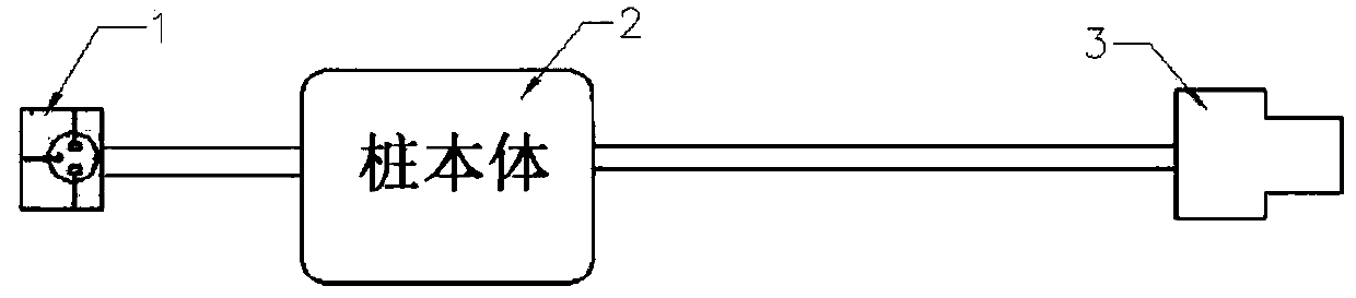
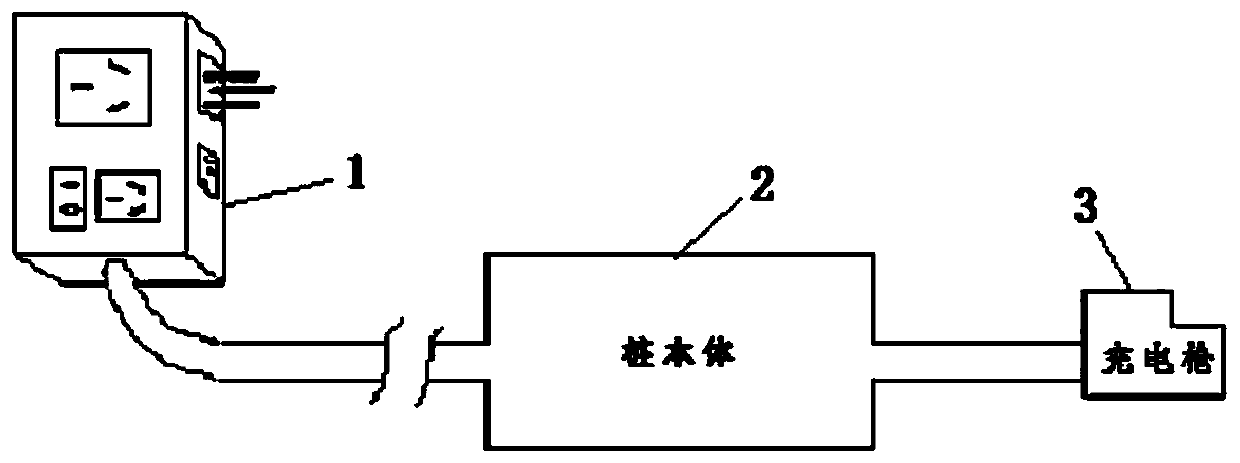
[0047] figure 2It is a schematic diagram of the structure of the charging pile in this embodiment, wherein the charging pile is specifically a new type of AC charging pile, and the two ends of the pile body 2 of the charging pile are respectively provided with a combined power connector 1 and a charging gun 3 .

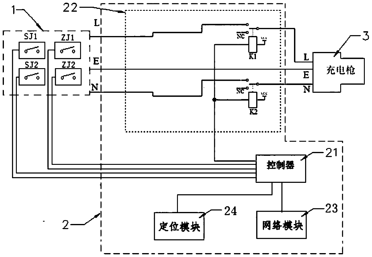
[0048] See image 3 , the combined power connector 1 and the charging gun 3 are connected through the single-phase wires (L wire, N wire, E wire) in the pile body 2 . A working circuit is provided inside the pile body 2 , and the working circuit includes a charging and discharging control circuit 22 and a controller 21 . The charging and discharging control circuit 22 is provided with two conventional relays K1 and K2, the relay K1 is connected in series in the L line of the single-phase electric wire, the relay K2 is connected in series in the N line of the single-phase electric wire, the controller in the pile body 2 21 controls the on / off of the relays K1 and K2...

Embodiment 2

[0071] Embodiment 2 is based on Embodiment 1, and replaces the combined power connector 1 in Embodiment 1 with a new type of combined power connector 1 with a compact structure, so as to achieve the purpose of reducing the size of the power connector.

[0072] The structure of the power connector 1 of the second embodiment will be specifically described below.

[0073] See Figure 10 , the power connector 1 has a top shell B1 and a bottom shell B2, and the top shell B1 is covered above the bottom shell B2. The left side of the top surface of the top shell B1 is a cover B31 of the 16A socket, and the 16A socket (not shown in the figure) is hidden under the cover B31. On the right side of the top surface of the top shell B1 is a 10A plug B4, which is a detachable structure, so it can be taken off. There is a 16A plug not shown in the figure below the 10A plug B4. After the 10A plug B4 is removed, the 16A plug can be pushed out to the original position of the 10A plug B4, so th...


PUM


Abstract

The invention relates to a charging pile and a power connector thereof. The power connector of the charging pile is provided with a pin and a socket, the pin is hidden in a shell of the power connector, the power connector is provided with a moving mechanism, and an operator enables the pin to extend out of the shell or be hidden in the shell through the moving mechanism. If a normal power supplyfunction of the charging pile needs to be implemented, the operator moves the pin out of the shell and then plugs the pin and a charging gun into an external power socket and an electric vehicle correspondingly, the pin triggers a pin state recognition switch when extending out of the shell, thus a working circuit operates in a charging gun output mode, and electrical energy flows to the charginggun from the pin; if a vehicle-vehicle interconnecting rescue function needs to be implemented, the operator retracts the pin into the shell and plugs the charging gun into the electric vehicle, thusthe electrical energy flows to the socket from the charging gun, and at the moment, other electric vehicles can be powered through the socket; and in the process of implementing vehicle-vehicle mutualrescue, even if the pin is charged, the pin is not mistakenly touched by the operator because the pin is hidden in the shell, and thus the electric shock hidden danger is avoided.

Description

technical field [0001] The invention relates to the technical field of charging piles, in particular to a new charging pile with a vehicle-vehicle interconnection function and a power connector thereof. Background technique [0002] Traditional charging piles (also known as chargers or chargers) are portable. This type of charging pile has low power, small size, light weight, easy to carry, and can be equipped with the car; there are also mobile charging piles. The power of this type of charging pile is slightly higher , heavy, with wheels for easy movement. [0003] The traditional charging pile belongs to the charging equipment for normal charging of electric vehicles, and its structure is generally as follows figure 1 As shown, one end of the pile body is connected to the combined power connector, and the other end is connected to the charging gun. This type of charging pile only has the function of taking power from the grid and charging the electric vehicle, and it ne...

Claims


Application Information

Patent Timeline
IPC IPC(8): B60L53/31B60L53/16
CPCB60L53/16B60L53/31Y02T10/70Y02T10/7072Y02T90/12Y02T90/14
Inventor 刘悦钟荣栋李同兵其他发明人请求不公开姓名
Owner ROCKING ENERGY INTELLIGENT TECH CO LTD
Why Eureka
Try Eureka