Buffer mechanism
A buffer mechanism and buffer plate technology, applied in the direction of mechanical equipment, springs, shock absorbers, etc., can solve the problems of environmental product pollution, complex structure, etc., and achieve the effect of low manufacturing and use costs and simple structure
- Summary
- Abstract
- Description
- Claims
- Application Information
AI Technical Summary
Problems solved by technology
Method used
Image

Examples
Embodiment
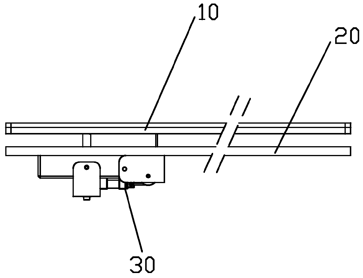
[0026] Such as figure 1 The buffer mechanism shown includes a buffer plate 10 and a support plate 20 placed in parallel, and a set of buffer units 30 mounted on the support plate. The number of buffer units is set according to requirements, and is not limited to one group.
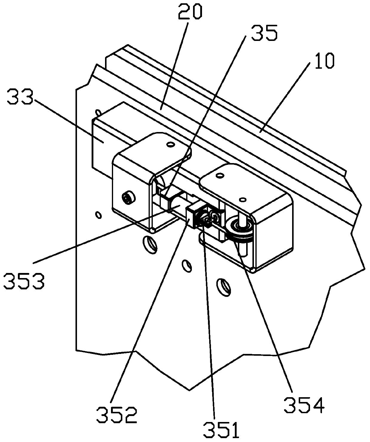
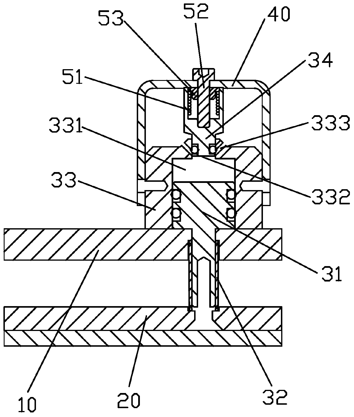
[0027] Such as figure 2 and 3 As shown, the buffer unit includes a first piston 31 , an elastic member 32 , a cavity 33 , a second piston 34 and a hook assembly 35 . The cavity is fixedly connected with the support plate. A chamber 331 is provided inside the chamber, the piston part of the first piston is located in the chamber, and the shaft part is connected with the buffer plate. The elastic member is a spring, which is installed between the buffer plate and the support plate and sleeved on the outside of the shaft portion of the first piston. The second piston 34 is located on the side of the first piston opposite to the buffer plate, and one end of the chamber corresponding to the second piston ...
PUM
 Abstract
Description
Claims
Application Information
 - R&D
- Intellectual Property
- Life Sciences
- Materials
- Tech Scout
- Unparalleled Data Quality
- Higher Quality Content
- 60% Fewer Hallucinations
Browse by: Latest US Patents, China's latest patents, Technical Efficacy Thesaurus, Application Domain, Technology Topic, Popular Technical Reports.
© 2025 PatSnap. All rights reserved.Legal|Privacy policy|Modern Slavery Act Transparency Statement|Sitemap|About US| Contact US: help@patsnap.com