Check patentability & draft patents in minutes with Patsnap Eureka AI!

Differential voltage-current conversion circuit

A differential voltage and current conversion technology, applied in logic circuit interface devices, logic circuit connection/interface layout, electrical components, etc., can solve problems such as suboptimal gain, low efficiency, and limited ADC circuit resolution

Active Publication Date: 2020-11-13
SOCIONEXT INC
View PDF7 Cites 0 Cited by
  • Summary
  • Abstract
  • Description
  • Claims
  • Application Information

AI Technical Summary

Problems solved by technology

[0018] Unfortunately, there are image 3 Drawbacks associated with the example circuit shown for voltage-to-current conversion
This voltage-to-current conversion is considered to be relatively inefficient in some applications, which limits the resolution of the overall ADC circuit employing sampler 42
Also, the gain associated with this conversion may not be optimal in some applications

Method used


Image

  • Differential voltage-current conversion circuit
  • Differential voltage-current conversion circuit
  • Differential voltage-current conversion circuit

Examples


Embodiment Construction

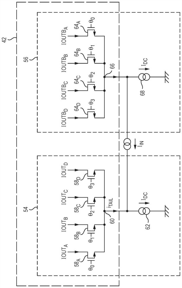
[0046] Figure 4 is a schematic diagram of the differential voltage-to-current conversion circuit 200 showing receiving a differential input voltage signal and outputting a corresponding differential current signal to the load circuit 300 .

[0047] The conversion circuit 200 is shown as effectively drawing current from a power supply voltage source VDDH (VDD high), where the current passes through the load circuit 300 (which has its own supply voltage source VDDL or VDD low, where VDDH>VDDL) Inject the ground (GND) power supply voltage source. However, the reverse is also possible, where current effectively flows from VDD (eg, VDDH) down through the load circuit 300 and then through the conversion circuit 200 .

[0048] Considering the current from Figure 1A The latter case indeed seems more appropriate.

[0049] However, in the same way, the sampler 42a corresponding to the sampler 42 can be used as Figure 1B Another way to effectively provide the overall configuration ...


PUM


Abstract

The present invention relates to circuits for voltage-current conversion, and in particular to differential voltage-current conversion circuits. Such a circuit is operable to receive a differential voltage input signal and output a corresponding differential current signal.

Description

technical field [0001] The present invention relates to circuits for voltage-to-current conversion, and in particular to differential voltage-to-current conversion circuits. Such a circuit is operable to receive a differential voltage input signal and output a corresponding differential current signal. Background technique [0002] To understand the potential uses of differential voltage-to-current conversion circuits, Figure 1A is a schematic circuit diagram of a four-phase (i.e. multi-phase) current-mode (current-steering) sampler 42 that closely corresponds to Figure 10 in EP-A1-2211468, and Figure 1A is just one example of a circuit configured to operate based on a differential current signal. [0003] The current mode sampler 42 is configured to sample the differential input signal current I by dividing the component current signal (at tail nodes 60 and 66 described later) into a series of current pulses (samples) as shown. IN Sampling is performed, and this series o...

Claims


Application Information

Patent Timeline
Patent Type & Authority Patents(China)
IPC IPC(8): G05F1/56H03K19/0175
CPCG05F1/561H03K19/017509H03F3/45179H03F3/45713H03F3/45717H03F2203/45008H03F2203/45078H03F2203/45306H03F2203/45418H03F2203/45431H03F2203/45642H03F1/0205H03F2200/129H03F2203/45116H03F2203/45151H03F2203/45258H03M1/002
Inventor 弗兰克·维尔纳乌韦·齐尔曼吉多·德罗奇安德烈·舍费尔
Owner SOCIONEXT INC
Features
  • R&D
  • Intellectual Property
  • Life Sciences
  • Materials
  • Tech Scout
  • Unparalleled Data Quality
  • Higher Quality Content
  • 60% Fewer Hallucinations
Learn More