Supercharge Your Innovation With Domain-Expert AI Agents!

Box-type transformer base with drainage structure

A technology of box-type transformer and drainage structure, which is applied in transformer/inductance parts, transformer/reactor installation/support/suspension, electrical component structure association, etc., which can solve the problems of high cost, heavy weight, and inconvenient handling and transportation.

Inactive Publication Date: 2019-07-26
浙江正宇智邦科技有限公司
View PDF3 Cites 2 Cited by
  • Summary
  • Abstract
  • Description
  • Claims
  • Application Information

AI Technical Summary

Problems solved by technology

At present, in order to prevent the box-type transformer from being submerged in rainy water, an upwardly protruding installation platform is generally poured at the installation position of the box-type transformer, but this platform is useless after the box-type transformer is removed, so some propose to use steel The installation platform of structural structure replaces the platform of pouring. The installation platform of steel structure can be transported to other places together with the box-type transformer, and no need to pour the platform again; The box-type transformer can only be raised by combining them together. However, the steel structure platform combined with multi-layer frames not only uses a lot of materials and costs a lot, but also has a large overall weight, which is not easy to transport and transport.

Method used


Image

  • Box-type transformer base with drainage structure
  • Box-type transformer base with drainage structure

Examples


Embodiment Construction

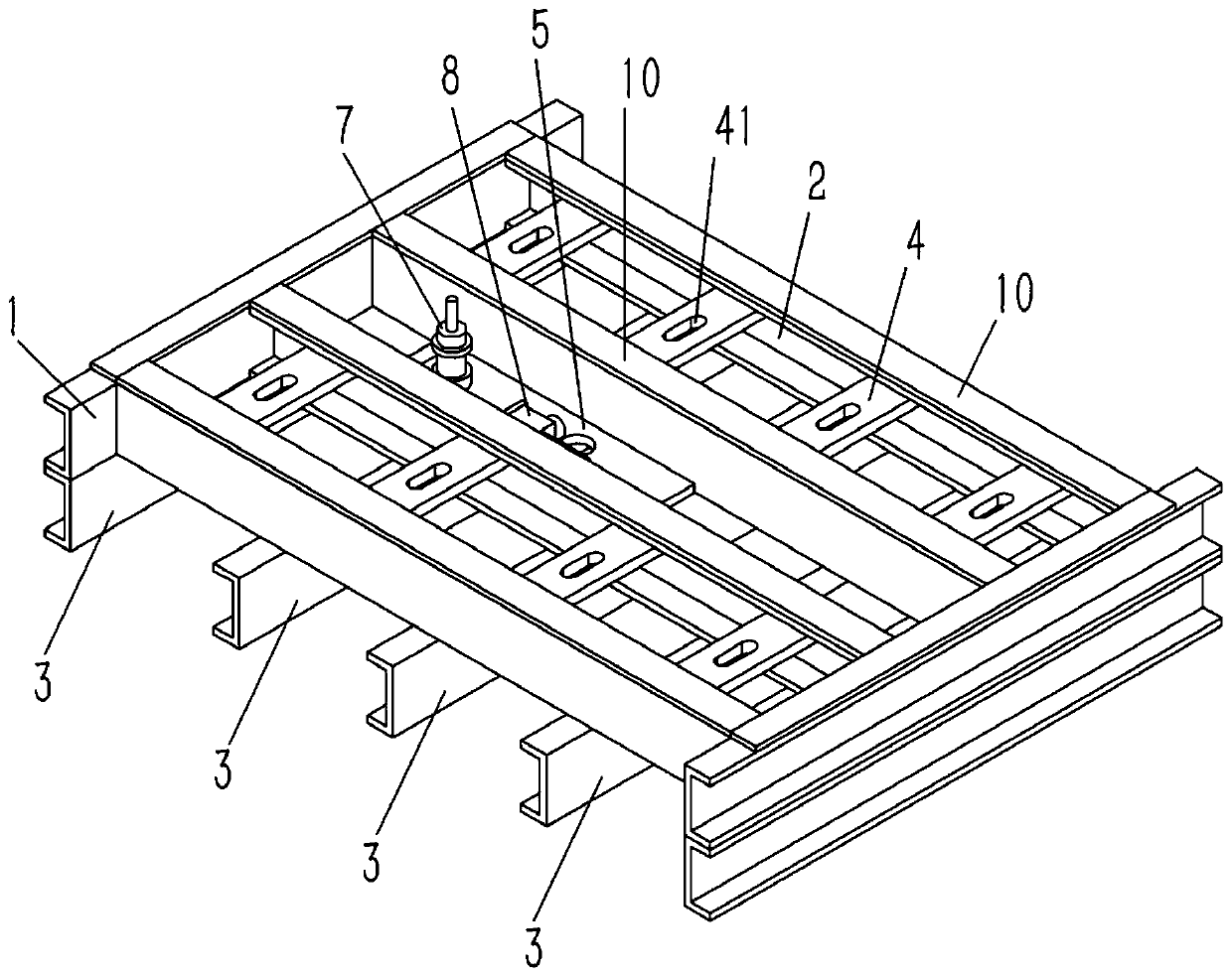
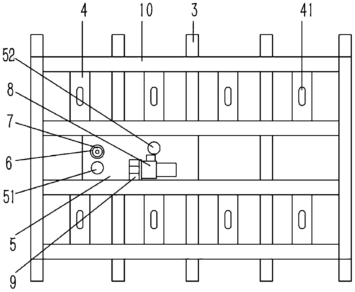
[0024] Example: see figure 1 , 2 As shown, a box-type transformer base with drainage structure includes an upper frame body, and the upper frame body includes first channel steels 1 opposite to each other longitudinally on both sides, and four horizontal second grooves are arranged between the first channel steels 1 Steel 2, the two ends of the second channel steel 2 are welded and fixed on the first channel steel 1, and the lower end faces of the second channel steel 2 and the first channel steel 1 are welded and fixed with some longitudinal third channel steels 3; A horizontal support plate 5 is arranged between the two second channel steels 2 in the middle of the first channel steel 1, and the support plate 5 is welded and fixed on the third channel steel 3, and the upper end surface of the support plate 5 is fixed with an annular The positioning sleeve 6 and the water pump mounting bracket 9 are fixed with a water pump 8 on the water pump mounting bracket 9, and the water...


PUM


Abstract

The invention discloses a box-type transformer base with a drainage structure. The box-type transformer base comprises an upper frame body, wherein the upper frame body comprises first steel channelswhich are longitudinally opposite to each other; four transverse second steel channels are arranged between the first steel channels, and the two ends of the second steel channels are welded and fixedon the first steel channels; a plurality of longitudinal third steel channels are fixedly welded on the lower end surfaces of the second steel channels and the first steel channels; a horizontal supporting plate is arranged between the two second steel channels in the middle of the first steel channels, and the supporting plate is welded and fixed on the third steel channels; a circular ring-shaped positioning sleeve and a water pump mounting bracket are fixed on the upper end surface of the supporting plate, and a water pump is fixed on the water pump mounting bracket; a water inlet and a water outlet of the water pump are fixedly connected with a water inlet pipe and a water discharging pipe respectively; and a water inlet and an outlet are formed in the supporting plate, and the waterinlet pipe and the water discharging pipe are inserted into the water inlet and the outlet of the supporting plate respectively. According to the box-type transformer base, on the basis of a steel structure platform, the drainage structure is additionally arranged on the steel structure platform, so that the box-type transformer can be conveniently immersed in water.

Description

[0001] Technical field: [0002] The invention relates to the technical field of box-type transformers, in particular to a box-type transformer base with a drainage structure. [0003] Background technique: [0004] Box-type transformers (usually referred to as "box transformers") concentrate the design of traditional transformers in box-type housings, with small size, light weight, low noise, low loss, and high reliability. They are widely used in residential quarters, commercial centers, light Stations, airports, factories, mines, enterprises, hospitals, schools and other places. At present, in order to prevent the box-type transformer from being submerged in rainy water, an upwardly protruding installation platform is generally poured at the installation position of the box-type transformer, but this platform is useless after the box-type transformer is removed, so some propose to use steel The installation platform of structural structure replaces the platform of pouring. ...

Claims


Application Information

Patent Timeline
IPC IPC(8): H01F27/06H01F27/40
CPCH01F27/06H01F27/402
Inventor 潘建礼
Owner 浙江正宇智邦科技有限公司
Features
  • R&D
  • Intellectual Property
  • Life Sciences
  • Materials
  • Tech Scout
  • Unparalleled Data Quality
  • Higher Quality Content
  • 60% Fewer Hallucinations
Learn More