Power cable take-up and pay-off device

A retractable device, power cable technology, applied to cable laying equipment, electrical components, etc., can solve the problems of difficult to control height, difficult to adjust the position, and inability to wrap cables in an orderly manner, to prevent loosening, facilitate transportation, and save money. human effect

Inactive Publication Date: 2019-08-02
STATE GRID CORP OF CHINA +1
View PDF6 Cites 9 Cited by
  • Summary
  • Abstract
  • Description
  • Claims
  • Application Information

AI Technical Summary

Problems solved by technology

[0004] The technical problem to be solved by the present invention is to provide a power cable retracting and unwinding device, which solves the inconvenience in the transfer of the cable shaft in the prior art, the difficulty in adjusting the position during winding, the difficulty in controlling the height, and the problems encountered in the winding process. The cable cannot be wound in an orderly manner, and the technical problem of loose winding

Method used


Image

  • Power cable take-up and pay-off device
  • Power cable take-up and pay-off device
  • Power cable take-up and pay-off device

Examples


specific Embodiment approach

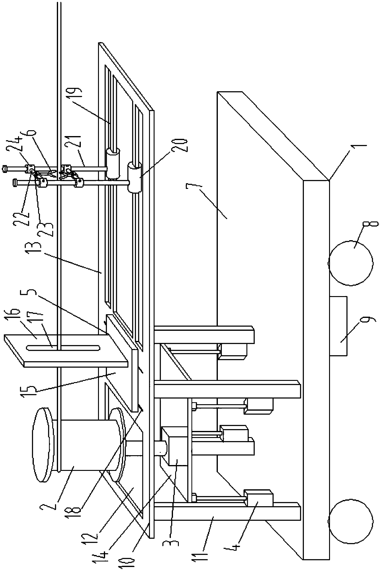
[0058] As a specific implementation of the power cable retracting device provided by the present invention, please refer to figure 1 , moving bodies include:

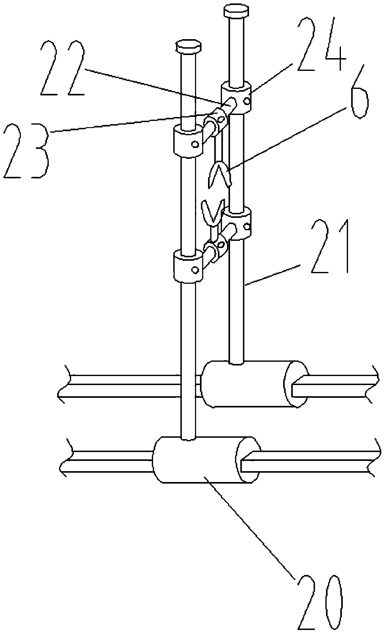
[0059] The sliding seat 20 is two respectively arranged on the two single rails of the double rail 19;

[0060] There are two vertical rods 21 and the bottom ends are respectively connected with two sliding seats 20;

[0061] The cross bar 22 is two and the two ends are slidingly connected to the two vertical bars 21 respectively, and is provided with a sliding limit mechanism;

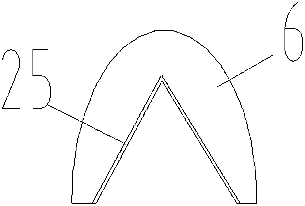
[0062] The middle sleeve 23 is arranged at the middle part of the cross bar 22 for connecting the chuck 6 .

[0063] In this embodiment, the sliding seat 20 is used to connect the double rail 19, and the double rail 19 is composed of two single rails, and the two sliding seats 20 are respectively used to connect a single rail, and are slidingly connected, and the sliding seat 20 plays the role of sliding and supporting .

[0064] In additio...


PUM


Abstract

The invention discloses a power cable take-up and pay-off device, and relates to the technical field of power cable layout. The power cable take-up and pay-off device comprises a traveling vehicle, atake-up roller, a guide frame and a cable clamp. The take-up roller is arranged on the traveling vehicle, the take-up roller is vertically arranged, the take-up roller is rotted through a first motorand lifted by an air cylinder, the guide frame is arranged on a cable take-up path on the take-up roller and is used for guiding take-up and pay-off of cables, the cable clamp is provided with two clamping heads with opposite clamping openings and facing towards the cables, the two clamping heads are arranged in a staggered mode in the direction perpendicular to the cables, and the clamping headsmove along the direction perpendicular to and parallel to the cables through a moving mechanism. The technical problems in the prior art that a cable shaft is inconvenient to transfer, the position isdifficult to adjust and the height is difficult to control during winding, the cables cannot be wound in order in the take-up process, and winding is loose are solved.

Description

technical field [0001] The invention relates to the technical field of power cable laying, in particular to a power cable retracting device. Background technique [0002] In the power supply system, as well as in the construction site, the cable is a very important piece of equipment. The cable is used for electricity transmission. It may need to be laid anytime and anywhere, and it is often not permanently fixed. It needs to be removed after use. However, the cable shaft is generally cumbersome, and cannot be quickly and effectively rewound and released by manual operation, which greatly reduces the speed of construction. [0003] In the prior art, the problems faced by using the cable shaft for retracting and unwinding are: 1. The transportation of the cable shaft is very inconvenient, and it cannot be quickly transferred to the receiving place; 2. The position of the cable shaft is difficult to adjust, and the height position is even more difficult. Transformation, 3. Th...

Claims


Application Information

Patent Timeline
Patent Type & Authority Applications(China)
IPC IPC(8): B65H75/42B65H75/44H02G1/06H02G3/00
CPCB65H75/425B65H75/4402B65H75/4439B65H75/4486B65H2701/34H02G1/06H02G3/00
Inventor 杨海运刘亚民郜志詹新明郭刚
Owner STATE GRID CORP OF CHINA
Why Eureka
Try Eureka