Joint in artificial limb for or thopaedic and orthopedic mechanism

A technology of joints and prosthetics, which is applied in the field of joints or rotary connection mechanisms, and can solve problems such as increased knee extension moment

Inactive Publication Date: 2003-02-12
奥托・伯克健康护理有限责任公司
View PDF5 Cites 0 Cited by
  • Summary
  • Abstract
  • Description
  • Claims
  • Application Information

AI Technical Summary

Problems solved by technology

However, this functional element has an important drawback: the knee extension moment generated by the action of the belt increases with increasing bending angle
Therefore, it is restricted to assume the sitting position without difficulty without additional technical measures (the prosthesis-knee joint is approximately in a 90° bent position) because the prosthesis is substantially unloaded in this body position. - the calf tends to return to its extended position

Method used


Image

  • Joint in artificial limb for or thopaedic and orthopedic mechanism
  • Joint in artificial limb for or thopaedic and orthopedic mechanism
  • Joint in artificial limb for or thopaedic and orthopedic mechanism

Examples


Embodiment Construction

[0040] For a better understanding of the present invention, at first the problem of the gene of the present invention will be described in conjunction with the prior art:

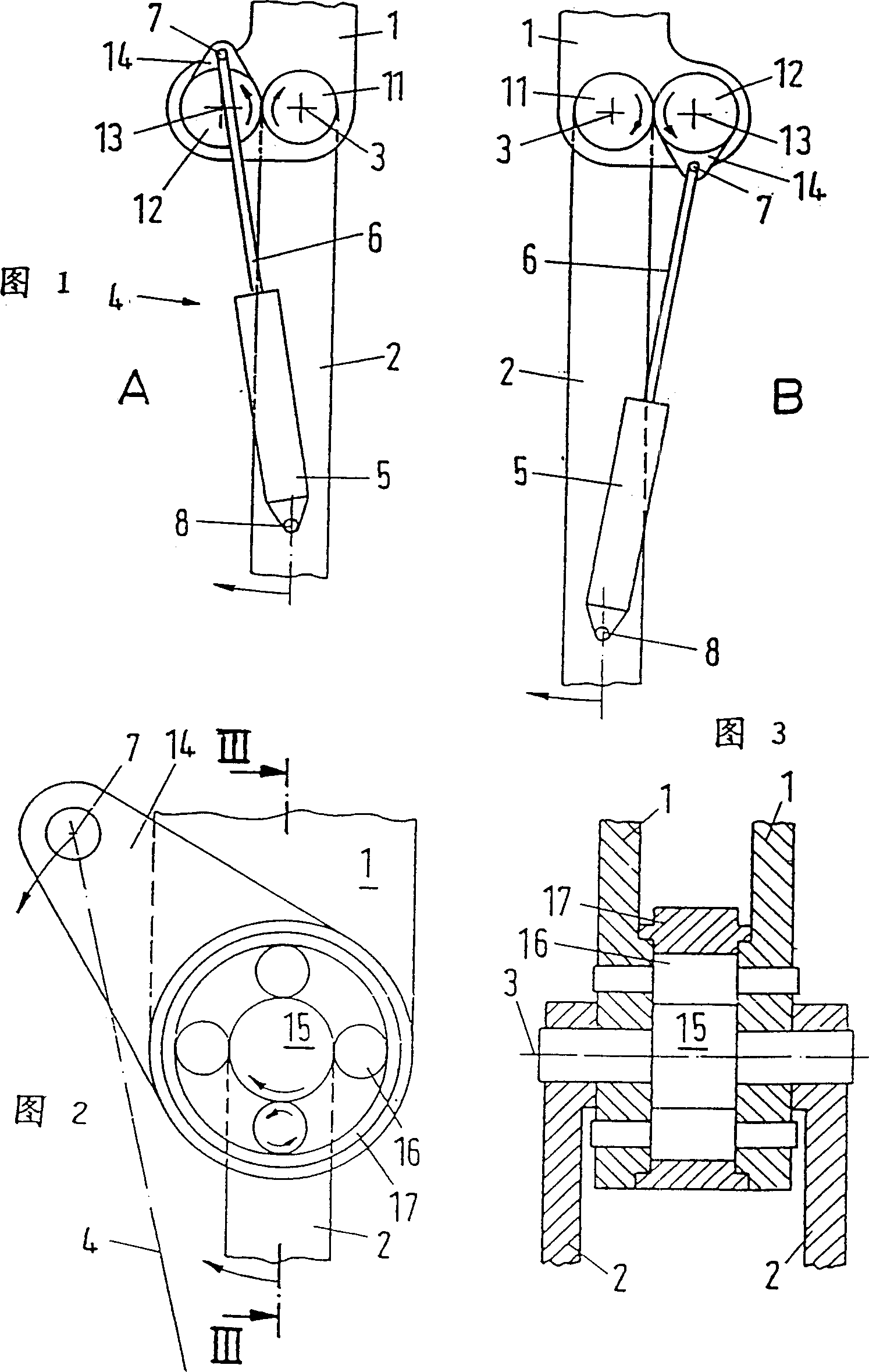
[0041] Figure 18 Including the left figure A and the right figure B, respectively represent a joint or a swing connection device, which includes a joint upper part 1, a joint lower part 2 and a joint shaft 3 that connects the two components 1, 2 to each other rotatably , the joint shaft 3 is fixedly connected with the lower joint part 2. This involves a single-center joint or a single-center swivel joint, described here in its straightened state. In addition, a control element 4 is provided, which in both exemplary embodiments is formed by a cylinder 5 with a piston rod 6 . The variable-length control element 4 is articulated with its upper end outside the joint upper part 1 and with its lower end on the joint lower part 2 . At the same time, the upper hinge point is marked with 7 and the lower hinge po...


PUM


Abstract

The invention relates to a joint or pivoting connection for orthopaedic prostheses and ortheses, which comprises a joint upper part, a joint lower part and, where appropriate, interposed guides and a control element which engages operatively on both sides of a joint member via a respective articulation point spaced apart from an articulation axle. To improve this the invention proposes that at least one of said articulation points be arranged so that its position can be varied relative to its articulation joint member and be kinematically connected to at least one other joint member via a mechanical forced coupling.

Description

technical field [0001] The present invention relates to joints or pivot joints in orthopedic prosthetics and orthopedic mechanisms, having an upper joint part, a lower joint part and optionally intermediately connected guide rods (hereinafter referred to as "joint components") and a control element, the control At both ends, the element effectively acts on a corresponding joint component (hereinafter referred to as “joint joint component”) via a joint point spaced apart from the joint axis. [0002] This joint can be a monocentric or polycentric prosthetic-knee joint, where the morphology of the individual joint components is not important. [0003] It does not matter within the scope of the invention whether the control element or the control system acts on a single joint or a single swivel connection or simultaneously on several joints or several swivel connections. Background technique [0004] Motion control of joints in orthopedic prosthetic and...

Claims


Application Information

Patent Timeline
IPC IPC(8): A61F2/58A61F2/60A61F2/64A61F2/66A61F2/74
CPCA61F2/605A61F2002/74A61F2/644A61F2/64A61F2/74
Inventor 伟富利特·A·克利格
Owner 奥托・伯克健康护理有限责任公司
Why Eureka
Try Eureka