

Geometric line drawing device
A geometric and line-drawing pen technology, applied in the field of geometric line-drawing devices, can solve the problems of not maintaining strength and unevenly drawn lines, etc., and achieve the effect of uniform lines
- Summary
- Abstract
- Description
- Claims
- Application Information
AI Technical Summary
Problems solved by technology
Method used
Image

Examples
specific Embodiment approach 1
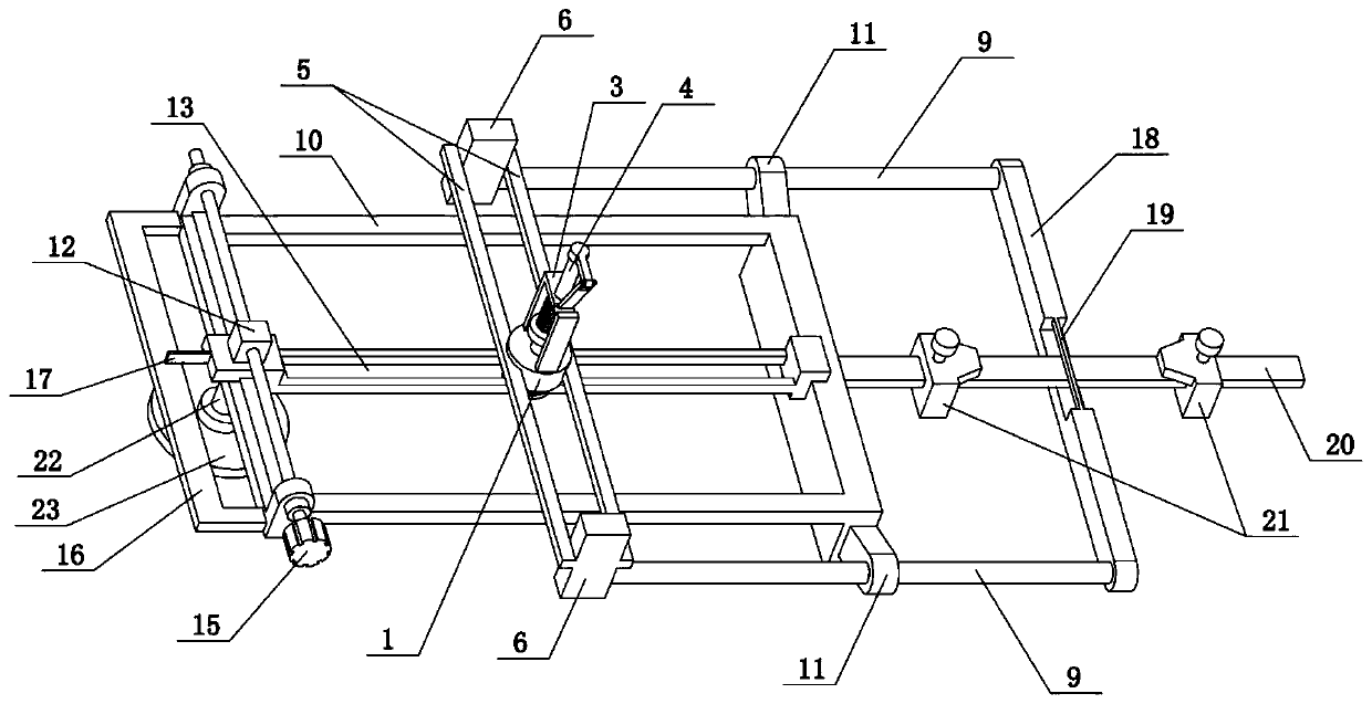
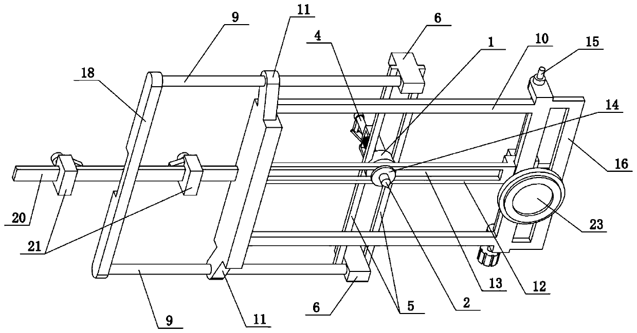
[0043] Combine below Figure 1-11To illustrate this embodiment, the present invention relates to a line drawing device, more specifically a geometric line drawing device, including a round seat 1, a line drawing pen 2, a door frame 3, a spring sleeve rod 4, and a slide rail rod 5 With block 6, the line-drawing pen 2 is always perpendicular to the paper surface. Compared with manual drawing, the brush will tilt irregularly with the hand. The lines drawn by the line-drawing mode perpendicular to the paper surface of the present invention are more uniform.
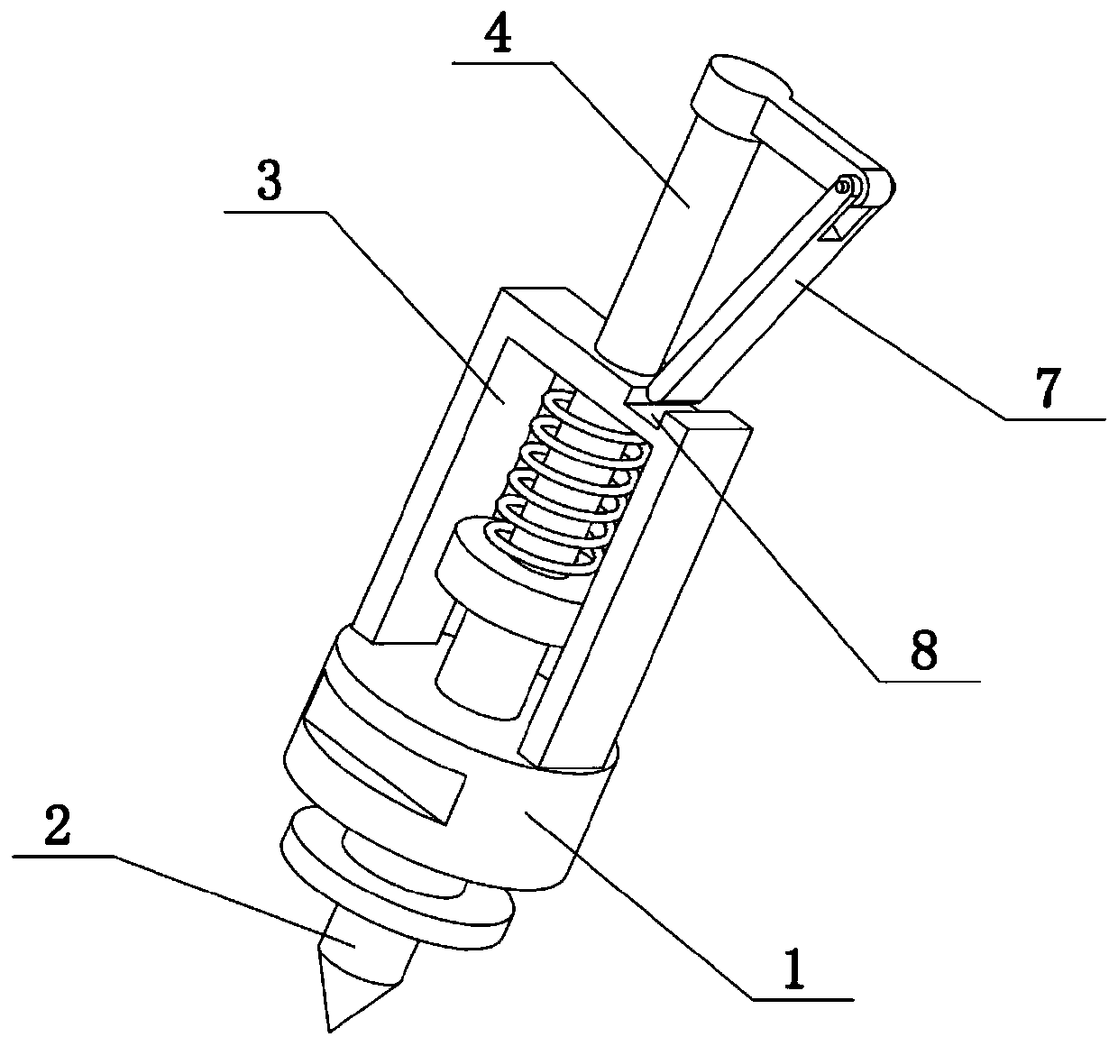
[0044] The line drawing pen 2 is vertically slidably connected on the round seat 1, the upper end of the round seat 1 is provided with a gantry 3, the spring sleeve rod 4 is vertically slidably connected to the upper end of the gantry 3, and the lower end of the spring sleeve rod 4 Fixedly connected to the upper end of the line drawing pen 2, the spring sleeve rod 4 is covered with a compression spring, the lower end of the s...
specific Embodiment approach 2
[0046] Combine below Figure 1-11 To illustrate this embodiment, the spring sleeve rod 4 can be pulled to the upper end and fixed in the following manner:
[0047] The upper end of the spring sleeve rod 4 is hingedly connected with a strut 7, the upper end of the portal frame 3 is provided with a draw-in groove 8, and the lower end of the strut 7 is against the draw-in groove 8, so that the spring sleeve rod 4 is pulled to the upper end and fixed; 7 can be rotated at the upper end of the spring sleeve rod 4. When the lower end of the support rod 7 is against the draw-in groove 8, the spring sleeve rod 4 is pulled to the upper end and supported, and then the line drawing pen 2 is lifted and fixed; so that the support rod 7 When leaving the draw-in slot 8, the spring sleeve lever 4 moves downward due to the force of the compressed spring, and then the line drawing pen 2 moves downward to contact the paper to draw a line.
[0048] Or, the spring sleeve rod 4 is provided with thr...
specific Embodiment approach 3
[0050] Combine below Figure 1-11 To illustrate this embodiment, the two seat blocks 6 are fixedly connected with horizontal round rods 9, the front and rear ends of the right end of the rectangular frame 10 are provided with protruding heads 11, and the two horizontal round rods 9 are respectively slidably connected to the two convex ends. On the head 11, the forward or backward movement of the round seat 1 is controlled by the front and rear translation bar 12. The left end of the front and rear translation bar 12 is slidably connected to the left end of the rectangular frame 10 through a chute structure. Pan bar 12 on. The two horizontal round rods 9 can slide leftward or rightward respectively on the two protrusions 11, and then drive the two seat blocks 6 and the two slide rail rods 5 to slide leftward or rightward, and then drive the round seat 1 and the drawer Slide the line pen 2 to the left or right, then the line pen 2 will draw a horizontal line on the paper.
[0...
PUM
 Abstract
Description
Claims
Application Information