
A method and device for controlling multi-axis synchronous motion of a robot

A multi-axis synchronization and robot technology, applied in program control, digital control, electrical program control, etc., can solve problems such as inability to efficiently calculate the shortest motion time

Active Publication Date: 2020-08-21
合肥欣奕华智能机器股份有限公司
View PDF12 Cites 0 Cited by
  • Summary
  • Abstract
  • Description
  • Claims
  • Application Information

AI Technical Summary

Problems solved by technology

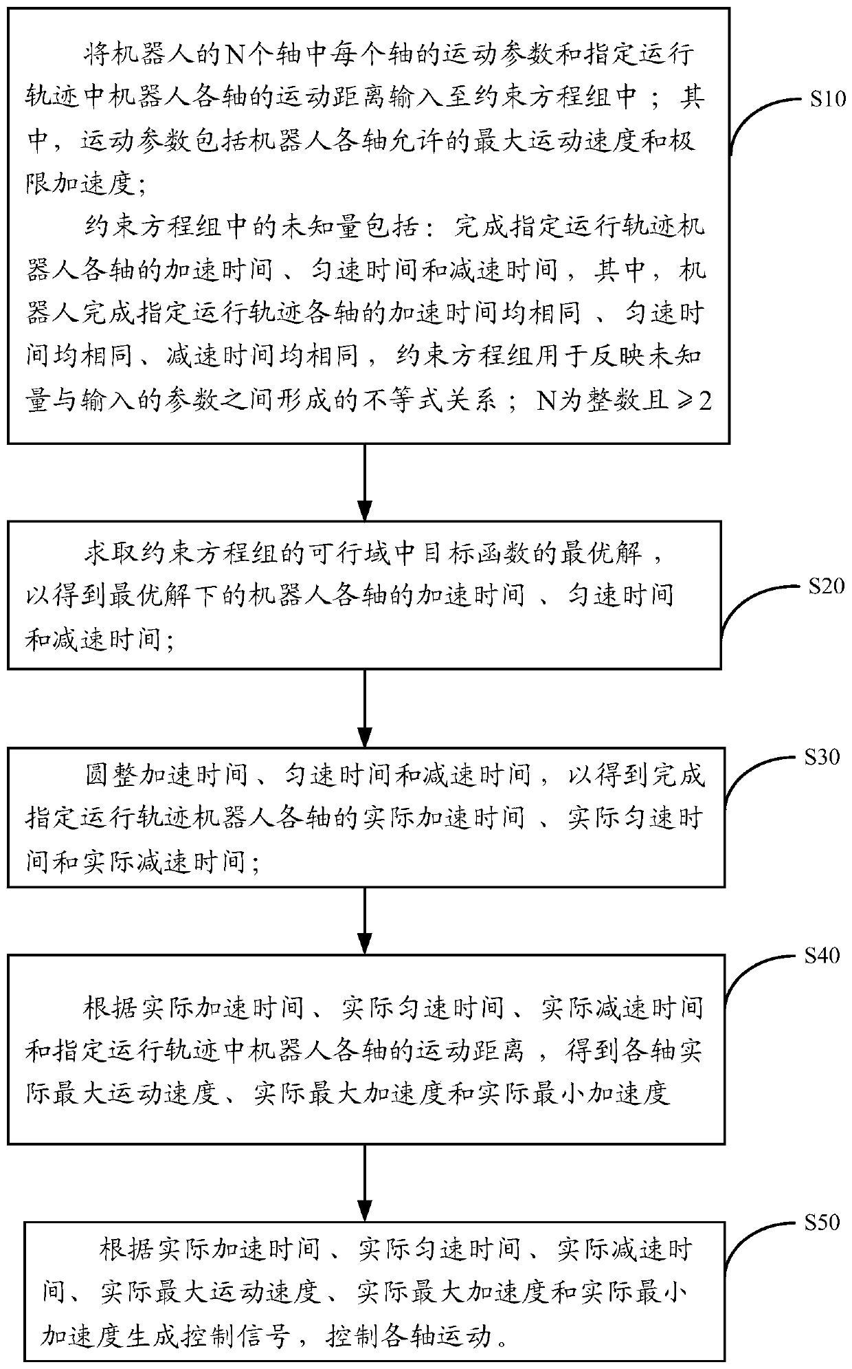
[0005] Embodiments of the present invention provide a method and device for controlling multi-axis synchronous motion of a robot, which can solve the problem in the prior art that it is impossible to efficiently calculate the shortest motion time of each axis under the premise of satisfying motion constraints

Method used


Image

  • A method and device for controlling multi-axis synchronous motion of a robot
  • A method and device for controlling multi-axis synchronous motion of a robot
  • A method and device for controlling multi-axis synchronous motion of a robot

Examples


Embodiment 1

[0074] The limit acceleration includes the maximum acceleration a 1max and minimum acceleration-a 2max , and in step S10, the input parameters include the maximum acceleration a 1max and minimum acceleration-a 2max .

[0075] In the first case, the set of constraint equations specifically includes:

[0076] Trapezoidal speed planning method: and motion constraints:

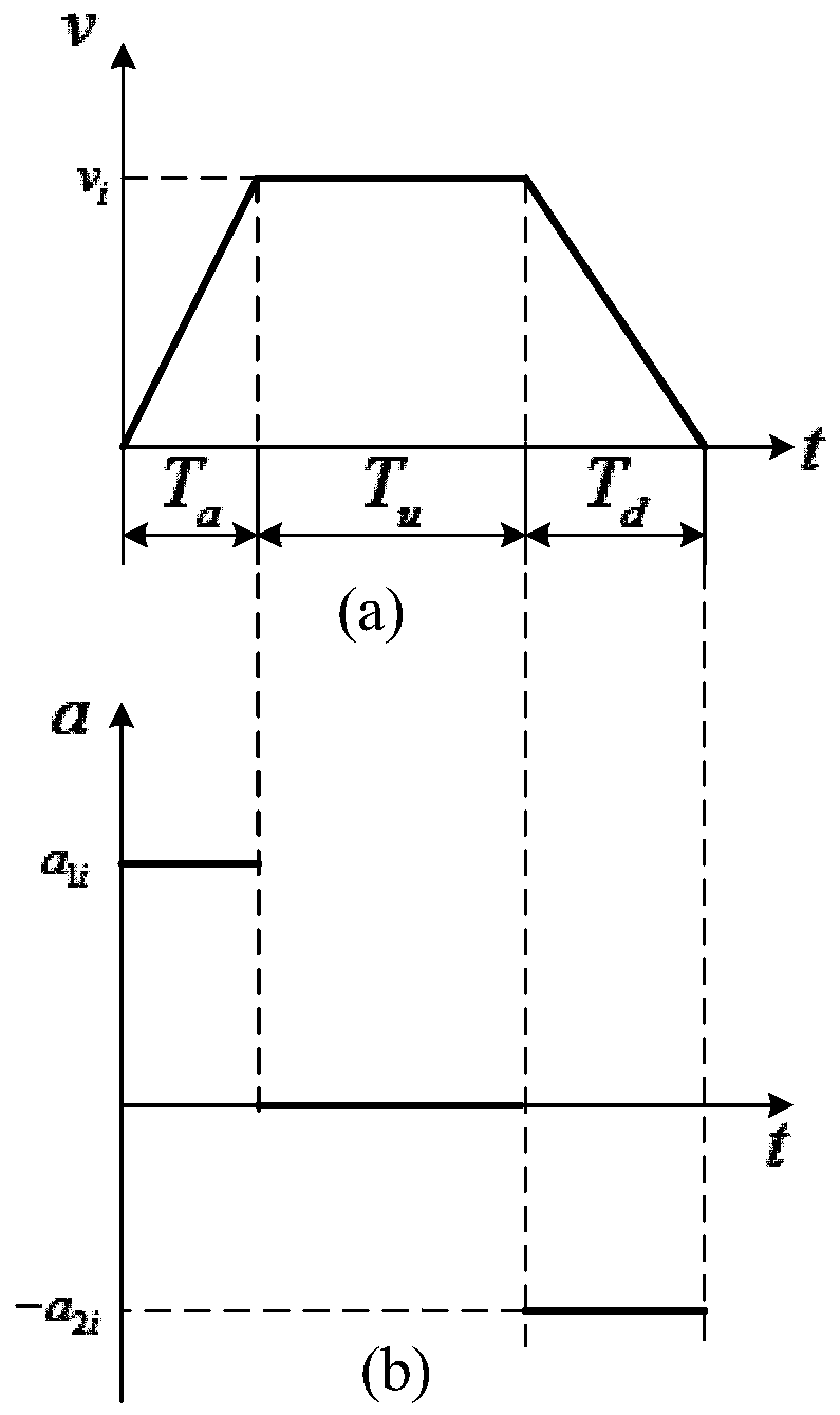
[0077] Among them, v i is the actual maximum movement speed of the i-th axis, a 1i is the actual maximum acceleration of the i-th axis, a 2i is the absolute value of the actual minimum acceleration of the i-th axis, D i is the movement distance of the i-th axis, v max,i is the maximum movement speed allowed by the i-th axis, a 1max,i is the maximum acceleration allowed by the i-th axis, a 2max,i is the absolute value of the minimum acceleration allowed by the i-th axis, i is an integer and 1≤i≤N.

[0078] Here, those skilled in the art should understand that the minimum acceleration allowed by the i...

Embodiment 2

[0165] input maximum acceleration a 1max and minimum acceleration-a 2max are equal in absolute value.

[0166] At this time, due to the input maximum acceleration a 1max and minimum acceleration-a 2max Therefore, when inputting the limit acceleration in step S10, you can only input one (only input the absolute value of the maximum acceleration or only the minimum acceleration), of course, you can also input both. When only one is entered, that is, the maximum acceleration of the i-th axis is equal to the absolute value of the minimum acceleration, such as Figure 4 As shown in (a) and (b), a 1i =a 2i ,T a =T d .

[0167] In the second case, the set of constraint equations specifically includes:

[0168] Trapezoidal speed planning method: and motion constraints: v i ≤v max,i , a 1i ≤a 1max,i ,T u ≥0, T a >0.

[0169] Among them, when the input is the maximum acceleration, a 1max,i is the maximum acceleration of the i-th axis; when the input is the minimum acc...

Embodiment 3

[0182] Motion parameters also include limit jerk; said limit acceleration includes maximum acceleration a 1max and minimum acceleration-a 2max ; The limit jerk includes the maximum jerk j 1max and minimum jerk-j 2max .

[0183] Among them, the maximum acceleration a 1max and the absolute value of the minimum acceleration a 2max May or may not be equal. Maximum jerk j 1max and the absolute value of the minimum jerk j 2max May or may not be equal.

[0184] In the third case, the set of constraint equations specifically includes: a double S-type speed planning method:

[0185] and motion constraints:

[0186] Among them, T a1 is the jerk time, T au is the uniform acceleration time, T a2 is the deceleration and acceleration time, T d1 is the acceleration and deceleration time, T du is the uniform deceleration time, T d2 is the deceleration time, D i is the movement distance of the i-th axis, v i is the actual maximum movement speed of the i-th axis, a 1i is t...


PUM


Abstract

The invention provides a method and device for controlling multi-axis synchronous motion of robots, relates to the technical field of artificial intelligence, and aims at solving the problem that theshortest time required for meeting the motion constraint and motion synchronization requirements cannot be calculated efficiently. The method comprises the steps of inputting a motion parameter of each of N axes of a robot and a motion distance of each axis of the robot in a specified running track into a constraint equation group, wherein N is an integer which is greater than or equal to 2; obtaining an optimal solution of a target function in a feasible domain of the constraint equation group so as to obtain an acceleration time Ta, a uniform speed time Tu and a deceleration time Td of eachaxis of the robot under the optimal solution; carrying out rounding to obtain an actual acceleration time, an actual uniform speed time and an actual deceleration time of each axis of the robot completing the specified running track; and generating a control signal according to the actual acceleration time, the actual uniform speed time, the actual deceleration time, an actual maximum motion speed, an actual maximum acceleration and an actual minimum acceleration to control the motion of each axis.

Description

technical field [0001] The invention relates to the technical field of artificial intelligence, in particular to a method and a device for controlling multi-axis synchronous motion of a robot. Background technique [0002] The robot is a multi-axis mechanism. When performing tasks, it often needs synchronous movement of all axes to ensure the stability of the movement. smoothness. [0003] In the prior art, the acceleration time, constant speed time, and deceleration time are usually given, and each axis is accelerated, constant speed, and decelerated according to the given time to achieve the purpose of multi-axis synchronization, but this method does not consider motion constraints, so , often lead to some axes can not meet the motion constraints or meet the constraints but cause a waste of motion time. There are also technicians who use the motion planning of a single axis according to the respective motion constraints of each axis, and then select the axis with the lon...

Claims


Application Information

Patent Timeline
Patent Type & Authority Patents(China)
IPC IPC(8): G05B19/416
CPCG05B19/4163G05B2219/36521
Inventor 曹柳芳何烽光王广炎
Owner 合肥欣奕华智能机器股份有限公司
Learn More