
Rationed fertilizing device with fertilizer mixing function

A quantitative fertilization and functional technology, applied in fertilization devices, fertilizer dispensers, applications, etc., can solve the problems of inconvenient use, difficulty in quantitative fertilization, and inability to mix two kinds of fertilizers, and achieve the effect of preventing splashing everywhere

Inactive Publication Date: 2019-08-23
张媛
View PDF4 Cites 15 Cited by
  • Summary
  • Abstract
  • Description
  • Claims
  • Application Information

AI Technical Summary

Problems solved by technology

[0003] The existing fertilization device cannot effectively mix the two kinds of fertilizers during the fertilization operation, and it is difficult to achieve quantitative fertilization, which is inconvenient to use

Method used


Image

  • Rationed fertilizing device with fertilizer mixing function
  • Rationed fertilizing device with fertilizer mixing function
  • Rationed fertilizing device with fertilizer mixing function

Examples


Embodiment 1

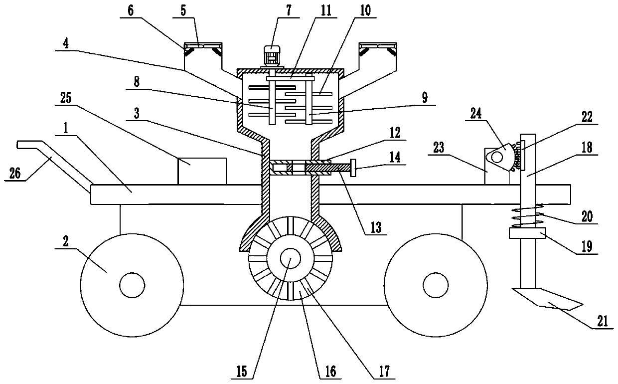
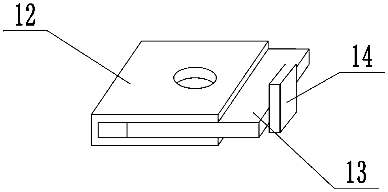
[0020] see Figure 1-3 , in an embodiment of the present invention, a quantitative fertilization device with a fertilizer mixing function includes a frame 1, a roller 2 and a mixing bin 3, the bottom of the frame 1 is equipped with a roller 2, and the left end of the frame 1 is equipped with a push rod 26. It is convenient to push the device to move the position. The mixing chamber 3 is installed on the frame 1, and the left and right ends of the top of the mixing chamber 3 are respectively installed with the feeding port 4. The top of the feeding port 4 is open, and the top of the feeding port 4 is installed with a movable plate. 5. There are two movable plates 5, which are symmetrically arranged left and right. The lower surface of the movable plate 5 is fixedly connected with a spring 6, and the lower end of the spring 6 is fixedly connected with the inner wall of the feeding port 4. The spring 6 is used to keep the movable plate 5 in a horizontal state. Two feeding ports 4...

Embodiment 2

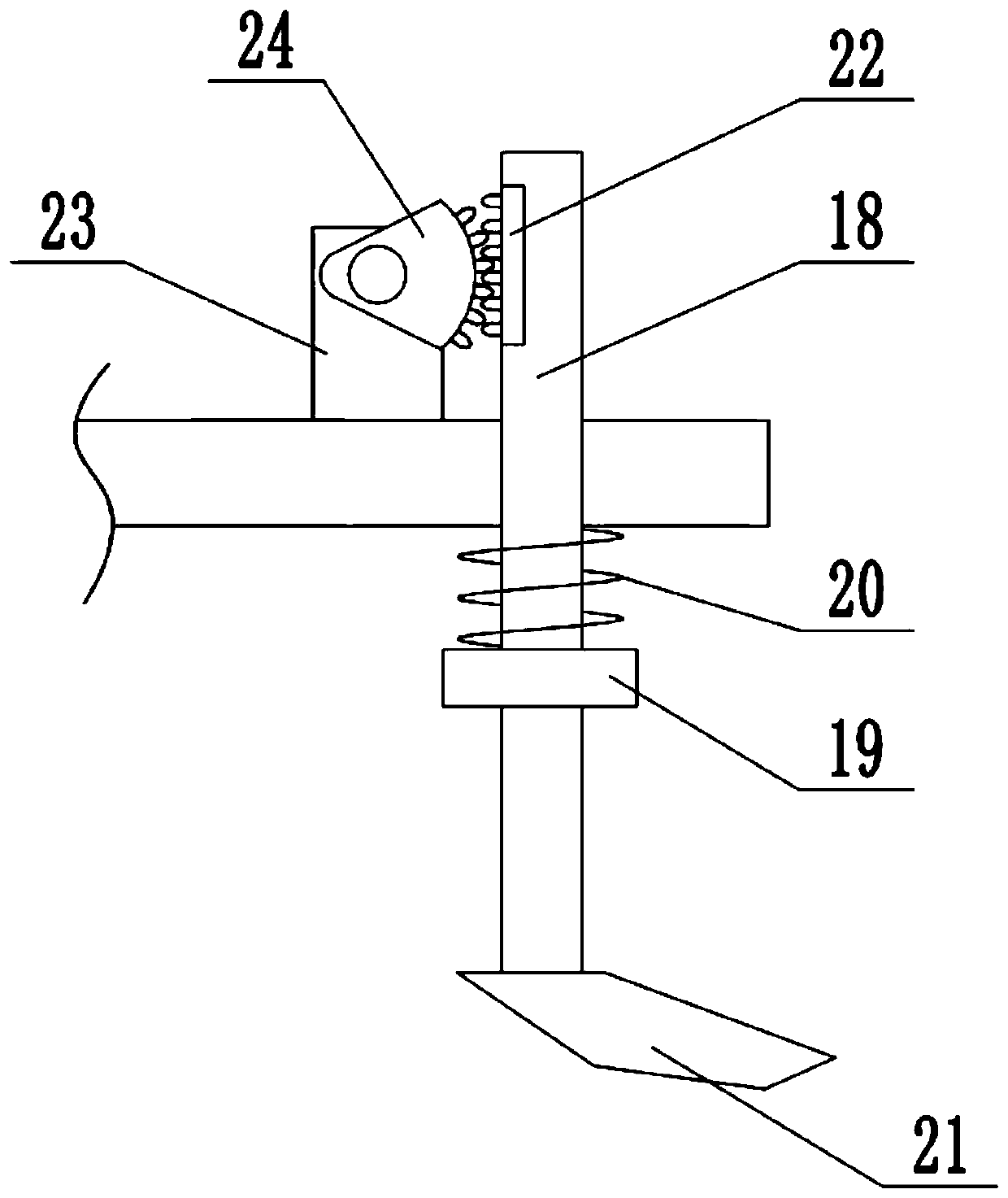
[0022] On the basis of Embodiment 1, a movable rod 18 is installed on the upper surface of the frame 1, the movable rod 18 runs through the frame 1, the movable rod 18 is slidably connected with the frame 1, the movable rod 18 can slide up and down, and the middle part of the movable rod 18 Boss 19 is processed, extension spring 20 is set on movable rod 18, the upper end of extension spring 20 is fixedly connected with the lower surface of frame 1, the lower end of extension spring 20 is fixedly connected with boss 19, and the lower end of movable rod 18 is installed Coulter 21 is arranged, and rack 22 is installed on the side wall of movable bar 18, and the left side of movable bar 18 is provided with driving motor 23, and driving motor 23 is fixedly connected with frame 1, and the axle extension end of driving motor 23 is fixedly connected with half The gear 24, the half gear 24 meshes with the rack 22, and the driving motor 23 drives the half gear 24 to rotate when it is run...


PUM


Abstract

The invention relates to the field of agricultural machinery and equipment, in particular to a rationed fertilizing device with a fertilizer mixing function. The rationed fertilizing device comprisesa frame, wheels and a mixing chamber. The mixing chamber is mounted on the frame, a stirring mechanism is mounted in the mixing chamber, an arc-shaped discharge outlet is arranged at the bottom of themixing chamber, a rotating shaft is mount in the discharge outlet, a discharge motor for driving the rotating shaft to rotate is mounted on the frame, the rotating shaft is sleeved with a dispensingdisc, and dispensing plates are radially distributed in the dispensing disc. The rationed fertilizing device has the advantages that different types of fertilizer can be fed into the mixing chamber atthe same time; a moving plate prevents the fertilizer from overflowing and scattering; the two types of fertilizer are stirred by the stirring mechanism to be mixed evenly; the fertilizer is enabledto drop evenly through the dispensing disc and the dispensing plates to achieve rationed fertilization; through a coulter capable of moving up and down, soil is stirred to make the fertilizer fully contact with the soil.

Description

technical field [0001] The invention relates to the field of agricultural machinery and equipment, in particular to a quantitative fertilization device with a fertilizer mixing function. Background technique [0002] Fertilizer refers to a class of substances that provide one or more essential nutrient elements for plants, improve soil properties, and increase soil fertility levels. It is one of the material bases of agricultural production. It mainly includes ammonium phosphate fertilizers, macroelement water-soluble fertilizers, medium element fertilizers, biological fertilizers, organic fertilizers, multi-dimensional field energy concentrated organic fertilizers, etc. Mixed fertilizers are obtained by mixing several single fertilizers, or a single fertilizer with binary or ternary compound fertilizers by mechanical means. Sometimes some fillers can be added to improve the physical and chemical properties of the fertilizer. For example, in order to prevent the excessive ...

Claims


Application Information

Patent Timeline
Patent Type & Authority Applications(China)
IPC IPC(8): A01C15/00A01C15/06A01C15/12A01C15/16A01C19/02
CPCA01C15/005A01C15/008A01C15/06A01C15/122A01C15/128A01C15/16A01C19/02
Inventor 张媛
Owner 张媛
Learn More