Disc pump impeller

A disc pump and impeller technology, applied in the design and manufacture of disc pump impellers, can solve problems such as excessive collision cutting, damage to guide vanes, damage to the integrity of transported materials, etc., to improve hydraulic performance, reduce cutting damage, and improve air. effect of corrosion

Pending Publication Date: 2019-08-23
XIHUA UNIV
View PDF1 Cites 2 Cited by
  • Summary
  • Abstract
  • Description
  • Claims
  • Application Information

AI Technical Summary

Problems solved by technology

The problem to be solved by the present invention is to propose a new disc pump impeller for the problems of excessive collision and cutting of the

Method used


Image

  • Disc pump impeller
  • Disc pump impeller
  • Disc pump impeller

Examples


Embodiment 1

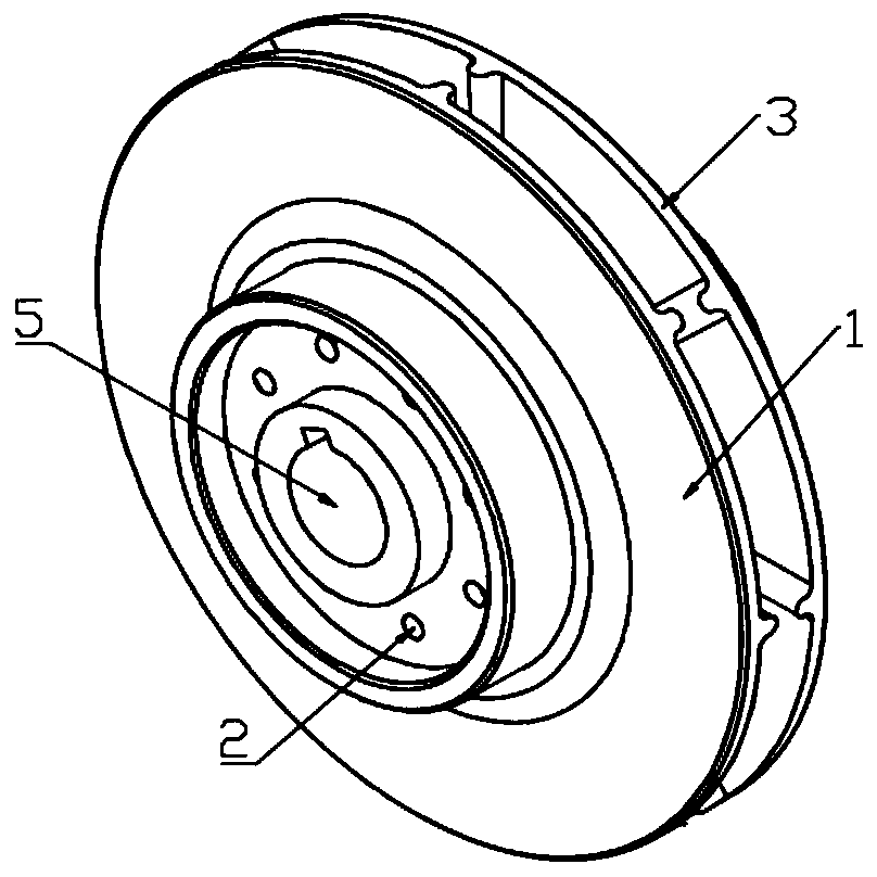
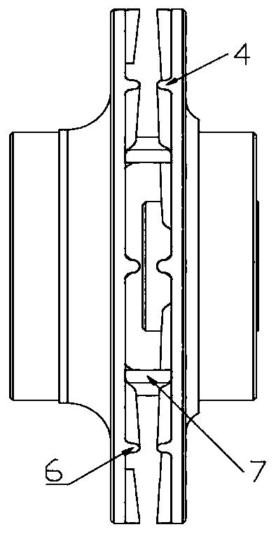
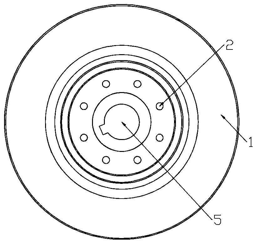
[0039] It includes the front cover 1 of the impeller and the balance hole 2 on the surface of the front cover 1 to balance the axial force. On the surface of the front cover 1, there is a hub 5 connected to the bearing of the generator and an arc-shaped front cover guide vane 4 , the front cover 1 is connected to the rear cover 3 through a cylindrical connection key 7, and there is a rear cover guide vane 6 similar to the front cover guide vane 4 on the rear cover 3

[0040] The balance hole 2 on the front cover plate 1 is used to balance the axial force generated by the impeller, reduce the wear of the bearing end face and the wear of the thrust plate, protect the bearing, the thrust plate and control the pump pressure. Wheel hub 5 is in order to cooperate with generator rotating bearing. The radius of the circle of the guide vane section of the front shroud guide vane 4 near the hub 5 is the smallest, and the radian is also the smallest. The radius and radian of the section ...

Embodiment 2

[0042] Referring to Embodiment 1, the other features remain unchanged, the short guide vane 8 of the front cover is added on the front cover 1, and the short guide vane 9 of the rear cover is added on the rear cover 3

Embodiment 3

[0044] It includes the front cover plate 1 of the impeller and the balance hole 2 on the surface of the front cover plate 1 for balancing the axial force. Nail-shaped front cover guide vanes 4, the front cover guide vanes 4 are evenly distributed in the radial direction, the front cover 1 is connected to the rear cover 3 through a cylindrical connection key 7, and the front cover guide vanes are connected to the front cover guide vanes on the rear cover 3 4 similar spike rear cover guide vanes 6

[0045] The balance hole 2 on the front cover plate 1 is used to balance the axial force generated by the impeller. It reduces the wear of the bearing end face and the wear of the thrust disc, which plays a role in protecting the bearing, the thrust disc and controlling the pump pressure. Wheel hub 5 is in order to cooperate with generator rotating bearing.


PUM


Abstract

The invention discloses a disc pump impeller. The disc pump impeller comprises a front cover plate, a rear cover plate, front cover plate guide vanes, rear cover plate guide vanes and a hub. The frontcover plate and the rear cover plate are connected through a connecting key, and the cross sections of the guide vanes are in the shapes of gradually varied arcs. The radius of the arcs is graduallyincreased from the center of the impeller to the periphery of the impeller. Through holes communicating with the front cover plate are symmetrically formed in the front cover plate and between the front cover plate guide vanes. The arcs of the guide vanes are tangent to the faces of the cover plates. According to the disc pump impeller, a smooth transition manner is adopted by the sections of thearc blades; when materials are conveyed, the contact angle between the materials and the guide vanes is small; compared with a traditional straight-blade disc pump, the efficiency is not reduced, andcutting damage to the materials is reduced; the long arc blades and the short arc blades are staggered, on the premise of not reducing the efficiency, the cavitation erosion performance of the disc pump is improved better, and the hydraulic performance of the pump is improved; and according to different conveyed materials, the integrity of the mater can be protected better through the nail-shapedblades on the basis that the transportation efficiency is not greatly changed.

Description

technical field [0001] The invention belongs to the technical field of fluid delivery pump design and manufacture, and in particular relates to a design and manufacture technology of a disc pump impeller. Background technique [0002] The disc pump is a centrifugal pump with a special impeller structure. The disc pump realizes energy conversion in the form of laminar flow. It has the advantages of stable unit operation, no clogging, small abrasion of the flow-passing parts, and long service life. It is widely used in petroleum industry abroad. , chemical, mining and other industries. [0003] Chinese application 201810687823.4 discloses a disc pump manufacturing method and a disc pump. The disc pump is transformed from a traditional centrifugal pump. Notches are set on the blades along the radial direction of the centrifugal pump, so that the flow channels between multiple blades are connected to each other. The viscous force of the fluid is used to pull the fluid for trans...

Claims


Application Information

Patent Timeline
IPC IPC(8): F04D29/22F04D29/44
CPCF04D29/2222F04D29/445
Inventor 张惟斌韩宇明江启峰张慧宇衡亚光刘小兵G·博华
Owner XIHUA UNIV
Why Eureka
Try Eureka