
A static balance test device for rotating parts

A technology for rotating parts and testing devices, applied in the field of static balance testing devices for rotating parts, can solve the problems of increasing static balance testing costs, requiring a large number of rotating shafts, and being prone to safety accidents, so as to improve static balance testing efficiency and improve testing efficiency. Efficient and easy to operate

Inactive Publication Date: 2019-10-29
HUNAN BIOLOGICAL & ELECTROMECHANICAL POLYTECHNIC
View PDF5 Cites 0 Cited by
  • Summary
  • Abstract
  • Description
  • Claims
  • Application Information

AI Technical Summary

Problems solved by technology

However, one rotating shaft only corresponds to the static balance test of one size and specification of rotating parts, and the size of the center hole of different sizes and specifications of rotating parts is different. Too much, resulting in a lot of waste and increasing the cost of static balance testing
At the same time, this traditional method is more suitable for rotating parts with a smaller diameter. For rotating parts with a larger diameter, such as a few meters, not only the cost of the rotating shaft is high, but the traditional method is to artificially move the rotating parts, resulting in inconvenient operation. prone to safety accidents

Method used


Image

  • A static balance test device for rotating parts
  • A static balance test device for rotating parts
  • A static balance test device for rotating parts

Examples


Embodiment Construction

[0024] In order to enable those skilled in the art to better understand the technical solution of the present invention, the present invention will be described in detail below in conjunction with the accompanying drawings. The description in this part is only exemplary and explanatory, and should not have any limiting effect on the protection scope of the present invention. .

[0025] It should be noted that like numerals and letters denote similar items in the following figures, therefore, once an item is defined in one figure, it does not require further definition and explanation in subsequent figures.

[0026] It should be noted that the orientation or positional relationship indicated by the terms "center", "upper", "lower", "left", "right", "vertical", "horizontal", "inner" and "outer" are Based on the orientation or positional relationship shown in the drawings, or the orientation or positional relationship that the inventive product is usually placed in use, it is onl...


PUM


Abstract

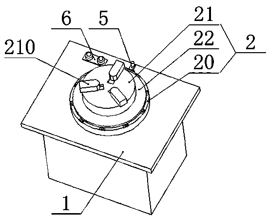
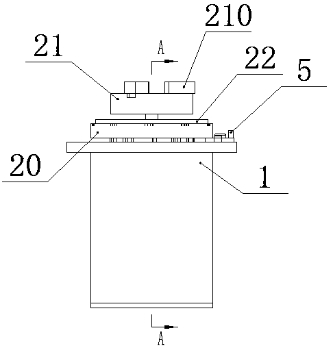
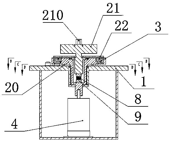
The invention discloses a rotary part static balance test device. The rotary part static balance test device comprises a worktable, a rotating mechanism, a centrifugal detecting mechanism and a driving mechanism; the rotating mechanism includes an active turntable and a passive turntable, and the active turntable is mounted on the worktable and is rotatably connected to the driving mechanism; oneend of the passive turntable is floatingly connected to the active turntable, and the other end is provided with a clamping portion for clamping rotary parts of different sizes and specifications; thecentrifugal detecting mechanism includes centrifugal blocks and first springs; the active turntable is uniformly provided with a plurality of grooves along the circumference; the centrifugal blocks are mounted in the grooves by the first springs; and the centrifugal blocks are connected to the passive turntable. The rotary part static balance test device realizes the automatic test of the rotarypart static balance, is convenient to operate, can be applied to the static balance test of the rotary parts of different sizes and specifications, saves the cost, is especially suitable for the static balance test of the large-sized rotary parts, and has high safety efficiency.

Description

technical field [0001] The invention relates to the technical field of static balance testing, in particular to a static balancing testing device for rotating parts. Background technique [0002] When performing static balance tests on rotating parts, the traditional method is to pass the rotating shaft through the center hole of the rotating part, and then support both ends of the rotating shaft on the support frame, and the rotating parts are in a suspended state. However, one rotating shaft only corresponds to the static balance test of one size and specification of rotating parts, and the size of the center hole of different sizes and specifications of rotating parts is different. If there are too many, it will cause a lot of waste and increase the cost of static balance test. At the same time, this traditional method is more suitable for rotating parts with a smaller diameter. For rotating parts with a larger diameter, such as several meters, not only the cost of the r...

Claims


Application Information

Patent Timeline
Patent Type & Authority Patents(China)
IPC IPC(8): G01M1/12
CPCG01M1/12
Inventor 廉良冲
Owner HUNAN BIOLOGICAL & ELECTROMECHANICAL POLYTECHNIC
Learn More