Image despinner based on FPGA

A derotator, image technology, applied in image communication, color TV parts, TV system parts and other directions, can solve problems such as viewing dizziness, and achieve visual fatigue, short imaging cycle, and high image resolution. Effect

Inactive Publication Date: 2019-08-23
BEIJING INST OF CONTROL & ELECTRONICS TECH
View PDF4 Cites 0 Cited by
  • Summary
  • Abstract
  • Description
  • Claims
  • Application Information

AI Technical Summary

Problems solved by technology

[0005] The purpose of the present invention is to provide an FPGA-based image derotator to solve the problem of viewing dizziness caused by the continuous shaking of the output image of the vehicle-mounted imaging device

Method used


Image

  • Image despinner based on FPGA

Examples


Embodiment Construction

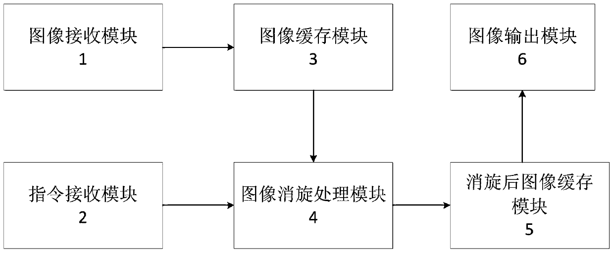
[0018] An FPGA-based image derotator, comprising: an image receiving module 1, an instruction receiving module 2, an image cache module 3, an image derotation processing module 4, an image cache module 5 and an image output module 6 after derotation;

[0019] The output end of the image receiving module 1 is connected to the input end of the image buffer module 3; the output end of the instruction receiving module 2 is connected to the input end of the image derotation processing module 4; the output end of the image buffer module 3 is connected to the input end of the image derotation processing module; The output end of the rotation processing module 4 is connected to the input end of the image buffer module 5 after derotation; the output end of the image buffer module 5 after derotation is connected to the input end of the image output module 6;

[0020] The function of the image receiving module 1 is to realize the connection between the image derotator and the image output...


PUM


Abstract

The invention discloses an image despinner based on an FPGA. The image despinner comprises an image receiving module (1), an image caching module (3), an instruction receiving module (3), an image despinning processing module (4) and an image output module (5). The image receiving module (1) communicates with a detector to realize image data receiving; the image caching module (2) is used for caching the received image data; the instruction receiving module (3) is used for receiving attitude information output by inertial measurement unit equipment and calculating a swinging angle of a detector during imaging, the image despinning processing module (4) is used for performing despinning processing according to the angle information and image data, and the image output module (5) is used forforming an image from an image despinning processing result and outputting the image. The method is used for solving the problem of appreciation dizziness caused by continuous swinging of images.

Description

technical field [0001] The invention relates to an image derotator, in particular to an image derotator based on FPGA. Background technique [0002] Imaging equipment is becoming more and more popular. It is not only used for filming and TV shooting, but even everyone with a mobile phone can shoot anytime, anywhere. During the shooting process, the holders of the imaging equipment take various measures to stabilize the camera during work, such as installing the camera on a slide rail for movement during film and television shooting, or installing the camera on a stable platform, etc., to ensure the quality of the shooting. The image does not shake, and there is no fatigue when viewing. [0003] With the improvement of digital signal processing capabilities and the improvement of the resolution of imaging equipment, more and more weapons and equipment based on image processing technology are used. Tanks, ships, etc. use high-resolution imaging equipment, and observers observ...

Claims


Application Information

Patent Timeline
Patent Type & Authority Applications(China)
IPC IPC(8): H04N5/21
CPCH04N5/21
Inventor 田野李龙华孙明熙陈磊王一平
Owner BEIJING INST OF CONTROL & ELECTRONICS TECH
Why Eureka
Try Eureka