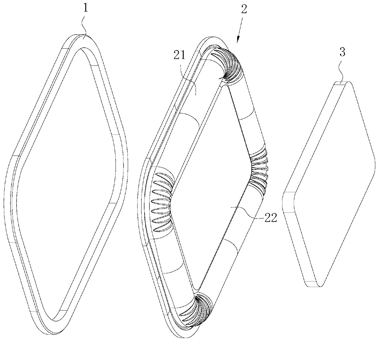
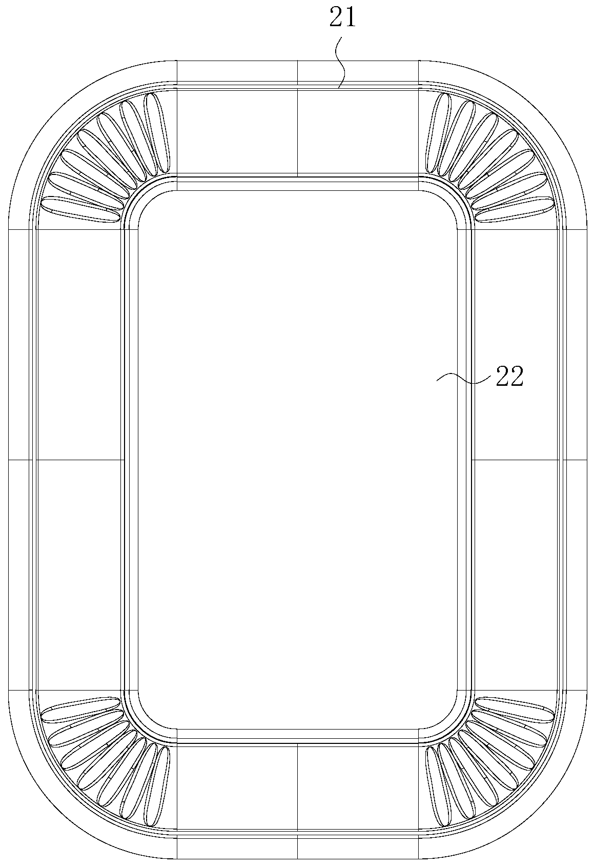
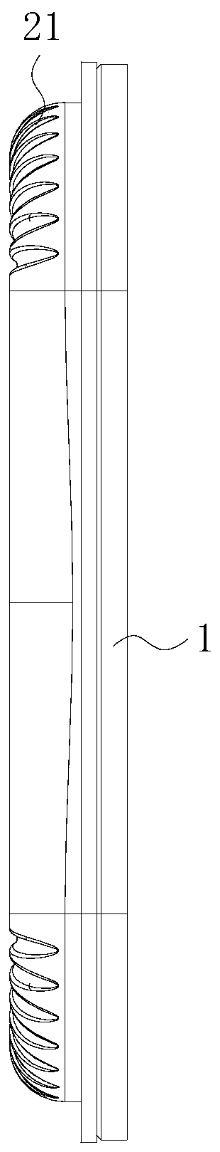
Passive radiator and manufacturing method thereof
A technology of passive radiators and manufacturing methods, which is applied in the direction of sensors, frequency/direction characteristic devices, electrical components, etc., and can solve the problems of weight overflow glue or seam separation, artificial cold bonding with low precision, and difficult quality assurance, etc. Achieve the effect of improving product quality
- Summary
- Abstract
- Description
- Claims
- Application Information
AI Technical Summary
Problems solved by technology
Method used
Image

Examples
Embodiment Construction
[0030] The technical solutions of the present invention will be further described below in conjunction with the drawings and specific implementations.
[0031] In the present invention, unless expressly stipulated and defined otherwise, the "above" or "below" of the first feature of the second feature may include the first and second features in direct contact, or may include the first and second features Not in direct contact but through other features between them. Moreover, the "above" of the first feature on the second feature includes the first feature directly above and obliquely above the second feature, or it simply means that the first feature is higher in level than the second feature. The "below" of the first feature under the second feature includes the first feature directly below and diagonally below the second feature, or it simply means that the level of the first feature is smaller than the second feature.
[0032] In addition, in the description of the present in...
PUM
 Abstract
Description
Claims
Application Information
PatSnap Eureka turns technology decisions into work you can execute. Powered by our Innovation Knowledge Graph, it runs expert workflows across engineering, life sciences, materials and intellectual property. Get your review-ready output in minutes.


