
Spray rod frame of self-propelled pesticide spraying machine

A self-propelled, spraying machine technology, applied in the device, application, animal husbandry and other directions of capturing or killing insects, can solve the problems of fatigue fracture of the boom, easy contact of the boom, damage, etc., and reduce maintenance costs. , The effect of ensuring work efficiency and prolonging service life

Pending Publication Date: 2019-08-27
山东佳尔能机电有限公司
View PDF0 Cites 2 Cited by
  • Summary
  • Abstract
  • Description
  • Claims
  • Application Information

AI Technical Summary

Problems solved by technology

[0003] The traditional suspension frame is assembled on the front of the sprayer in a fixed way, and the structure of the folding mechanism between the multi-section spray boom frames is relatively simple and the stability is poor
When working in the field, the total length of the spray boom is several meters or even more than ten meters after it is fully deployed. Since the sprayer often needs to turn and avoid obstacles such as utility poles, the spray boom is easy to touch the ground or hit obstacles and cause damage.
In addition, the field ground is uneven, and the sprayer often shakes from side to side, which may also easily lead to fatigue and fracture of the spray boom.
Therefore, the failure rate of the spray rod of the existing spraying machine is high, and the service life is short, which not only increases the maintenance cost of the user, but also delays work and time, which affects the efficiency of the spraying operation

Method used


Image

  • Spray rod frame of self-propelled pesticide spraying machine
  • Spray rod frame of self-propelled pesticide spraying machine
  • Spray rod frame of self-propelled pesticide spraying machine

Examples


Embodiment

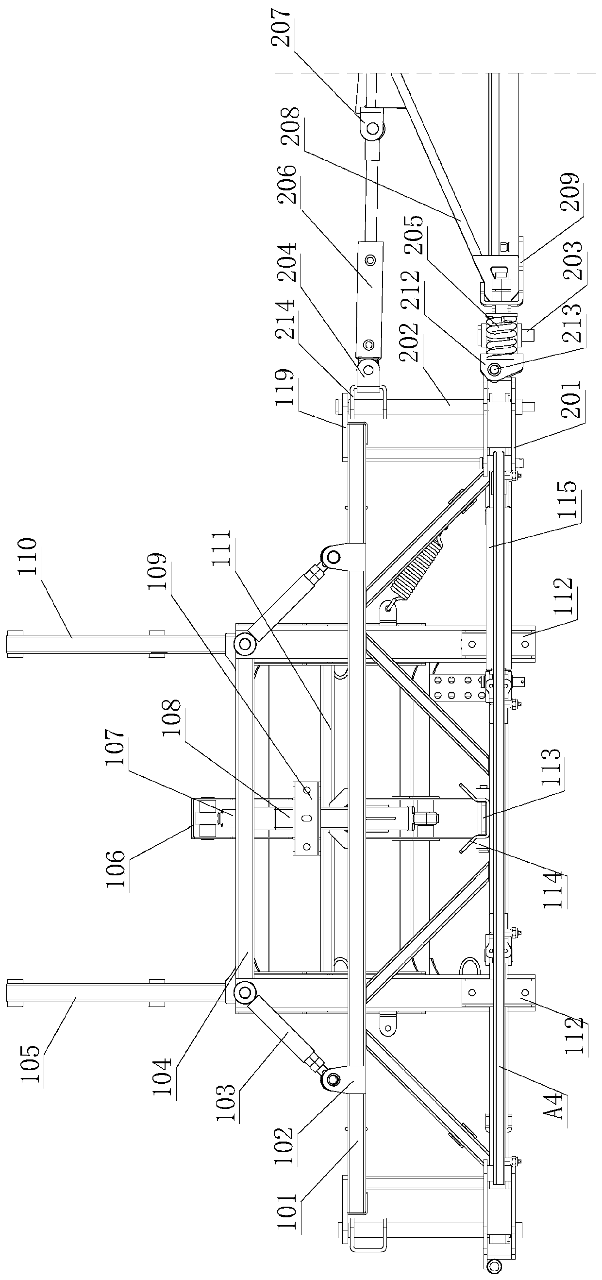
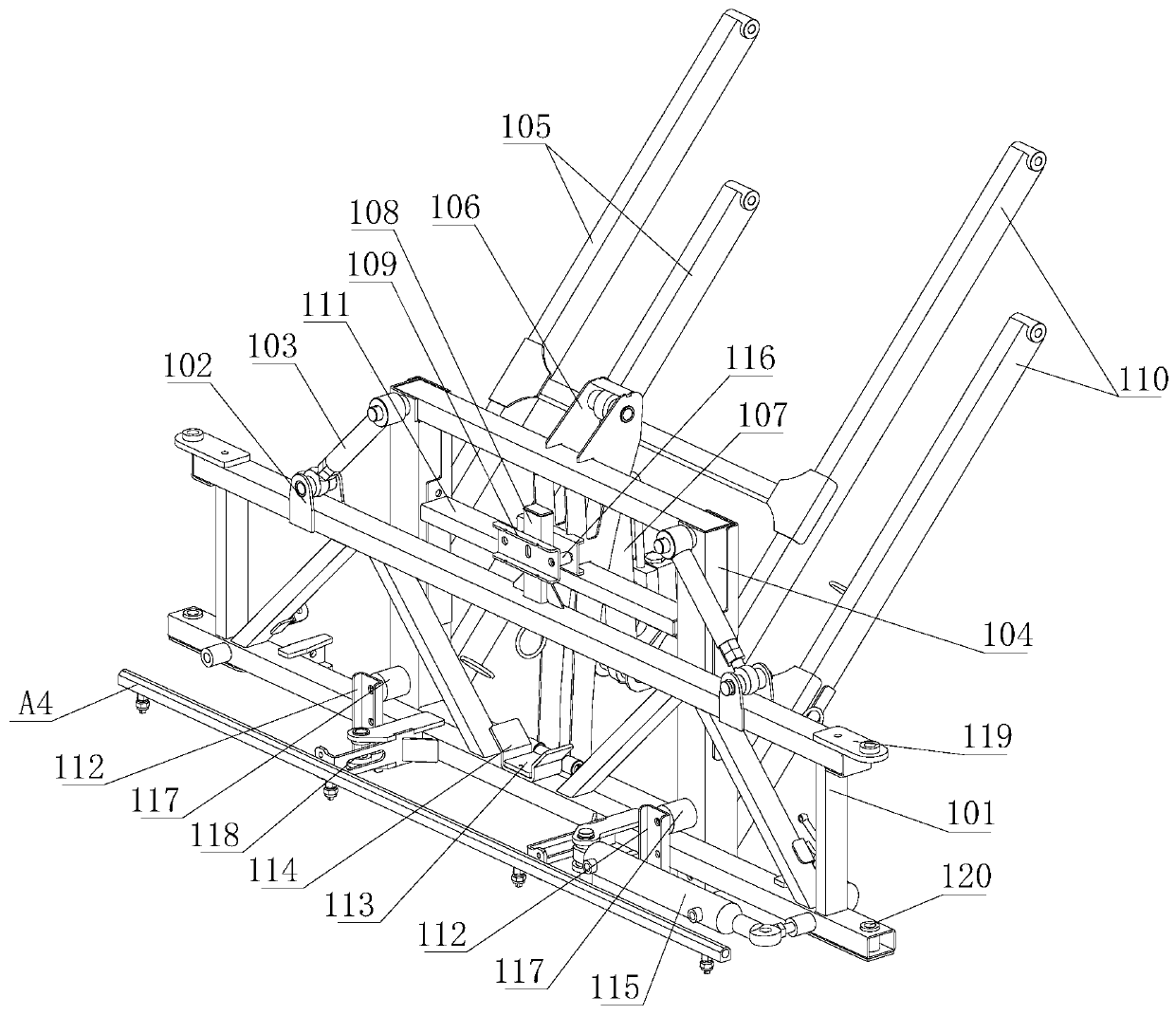
[0031] refer to figure 1, the spray boom frame of the self-propelled spraying machine described in this embodiment includes a suspension frame 1, a first side spray boom frame 3 for installing the first section of the side spray boom A1, and is installed on the suspension frame 1 and the first side The first folding mechanism 2 between the spray boom frames 3, the second side spray boom frame 5 for installing the second side spray boom A2, and the second side spray boom frame 5 installed between the first side spray boom frame 3 and the second side spray boom frame 5 The second folding mechanism 4 between them, and the third folding mechanism 6 for connecting the second section of the side spray bar A2 and the third section of the side spray bar A3; the front side of the suspension frame 1 is provided with a middle spray bar A4 The middle spray boom frame 118 of. As we all know, the spray boom frame of the self-propelled spraying machine includes a suspension frame located at...


PUM


Abstract

The invention relates to the technical field of self-propelled pesticide spraying equipment, in particular to a spray rod frame of a self-propelled pesticide spraying machine. The frame comprises a suspension frame, a first side spray bar frame used for mounting a first section of a side spray bar, a first folding mechanism mounted between the suspension frame and the first side spray bar frame, asecond side spray bar frame used for mounting a second section of the side spray bar, a second folding mechanism mounted between the first side spray bar frame and the second side spray bar frame, and a third folding mechanism used for connecting the second section of the side spray bar with a third section of the side spray bar; and an intermediate spray bar frame is arranged on the front side of the suspension frame and used for mounting an intermediate spray bar. The spray bar frame can greatly reduce the failure rate of the spray bar, prolong the service life of the spray bar, reduce themaintenance cost of users, and ensure the spraying operation efficiency.

Description

technical field [0001] The invention relates to the technical field of self-propelled spraying equipment, in particular to a spray boom frame of a self-propelled spraying machine. Background technique [0002] Self-propelled spraying machines are generally equipped with very long spray booms in order to achieve wide spray width and high work efficiency. When working in narrow fields, part of the spray boom needs to be folded to enhance maneuverability; in addition, when working in the field When finished, the boom needs to be stored for easy transportation. Therefore, the self-propelled spraying machine generally all installs a suspension frame at the front portion of the vehicle frame, and a multi-section foldable spray boom frame is respectively assembled on both sides of the suspension frame. [0003] The traditional suspension frame is fixedly installed on the front of the sprayer, and the structure of the folding mechanism between the multi-section spray boom frames is...

Claims


Application Information

Patent Timeline
Patent Type & Authority Applications(China)
IPC IPC(8): A01M7/00
CPCA01M7/0064A01M7/0075
Inventor 叶金峰
Owner 山东佳尔能机电有限公司
Learn More