
Automatic regulating structure for bending part of endoscope

A technology of automatic adjustment and bending, applied in the field of endoscopy, can solve problems such as time-consuming and laborious, inconvenient operation, and impact on diagnosis, and achieve the effects of reducing discomfort, improving control accuracy, and convenient operation

Pending Publication Date: 2019-08-27
CHONGQING JINSHAN SCI & TECH GRP
View PDF0 Cites 4 Cited by
  • Summary
  • Abstract
  • Description
  • Claims
  • Application Information

AI Technical Summary

Problems solved by technology

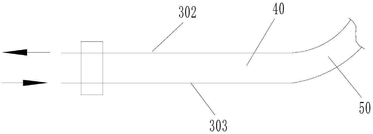
[0003] as attached figure 2 As shown, taking the up and down bending of the bending part as an example, the bending part 50 can move up and down under the action of the first steel wire 302 and the second steel wire 303, as shown in the figure, the first steel wire 302 is tightened, and the second steel wire 303 is loosened , the bending part 50 bends upwards, but when the mirror body is used for a period of time, the steel wire will be looser than the initial state due to various reasons. When the first steel wire 302 is relaxed and then subjected to tension, the upward bending angle of the bending part 50 will be smaller than the expected value. It will cause the observation range of the mirror body in the body cavity to become smaller, which will affect the diagnosis. After the problem is found, the solution in the prior art is to manually adjust the tightness of the steel wire. , the steps are cumbersome, time-consuming and labor-intensive, and inconvenient to operate

Method used


Image

  • Automatic regulating structure for bending part of endoscope
  • Automatic regulating structure for bending part of endoscope
  • Automatic regulating structure for bending part of endoscope

Examples


Embodiment Construction

[0034] The present invention will be further described in detail below in conjunction with test examples and specific embodiments. However, it should not be understood that the scope of the above subject matter of the present invention is limited to the following embodiments, and all technologies realized based on the content of the present invention belong to the scope of the present invention.

[0035] In describing the present invention, it should be understood that the terms "longitudinal", "transverse", "upper", "lower", "front", "rear", "left", "right", "vertical", The orientation or positional relationship indicated by "horizontal", "top", "bottom", "inner", "outer", etc. are based on the orientation or positional relationship shown in the drawings, and are only for the convenience of describing the present invention and simplifying the description, rather than Nothing indicating or implying that a referenced device or element must have a particular orientation, be cons...


PUM


Abstract

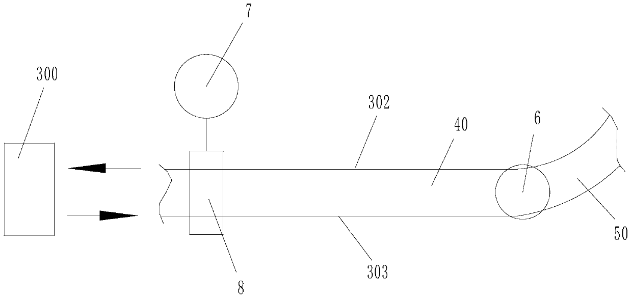
The invention discloses an automatic regulating structure for a bending part of an endoscope. The automatic regulating structure comprises an operation part, an insertion part and the bending part which are connected in sequence; the operation part is provided with a control hand wheel; an angle sensor is arranged at a connecting position of the insertion part and the bending part; a first steel wire and a second steel wire are arranged in the insertion part and the bending part; the control hand wheel is separately connected with the first steel wire and the second steel wire through a transmission mechanism; tightness adjusting mechanisms are arranged on positions, corresponding to the first steel wire and the second steel wire, on the transmission mechanism; the automatic regulating structure further comprises a detection control part; the detection control part is electrically connected with the angle sensor and the tightness adjusting mechanisms separately. According to the technical scheme of the invention, the tightness degree of steel wires can be automatically adjusted without taking an endoscope body apart, so that the control precision of the bending part is improved; operation of a doctor is convenient; the efficiency is improved; meanwhile, the discomfort of a patient is relieved.

Description

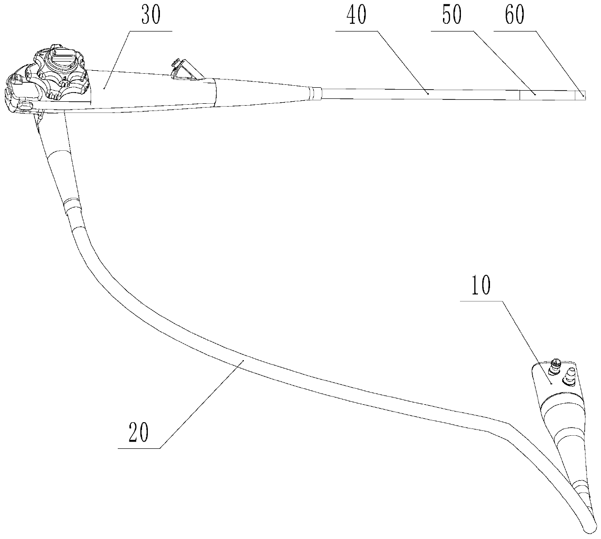
technical field [0001] The invention relates to the technical field of endoscopes, in particular to an automatic adjustment structure of an endoscope bending part. Background technique [0002] Such as figure 1 , for endoscopes widely used in the medical field, the endoscope body generally consists of a light guide part 10 , a universal cable part 20 , an operation part 30 , an insertion part 40 , a bending part 50 and a head end part 60 . The bending part 50 is generally controlled by four steel wires through the two handwheels of the operating part 30 to move up, down, left and right in four directions, one of which controls the up and down bending movement, and the other controls the left and right directions. , right bending movement, the control principle and action process of the bending part 50 bending up, down, left, and right in four directions are the same. After the endoscope is used for a period of time, the steel wire may be loose due to wear and aging. [000...

Claims


Application Information

Patent Timeline
IPC IPC(8): A61B1/005
CPCA61B1/0058
Inventor 孙宇邓安鹏周健
Owner CHONGQING JINSHAN SCI & TECH GRP
Learn More