
Power transmission protection mechanism for rail crane

A technology of power transmission and protection mechanism, applied in the field of rail cranes, can solve the problem that the torque arm system cannot play the role of buffering and shock absorption, and achieve the effect of avoiding overturning and rolling

Active Publication Date: 2019-08-27
QINGDAO PORT INT +1
View PDF5 Cites 0 Cited by
  • Summary
  • Abstract
  • Description
  • Claims
  • Application Information

AI Technical Summary

Problems solved by technology

[0003] The object of the present invention is to provide a power transmission protection mechanism used on rail cranes to solve the defect that the torsion arm system on the existing rail cranes cannot provide effective buffering and shock absorption protection

Method used


Image

  • Power transmission protection mechanism for rail crane
  • Power transmission protection mechanism for rail crane
  • Power transmission protection mechanism for rail crane

Examples


Embodiment Construction

[0023] In order to make the purpose, technical solutions and advantages of the embodiments of the present invention clearer, the technical solutions in the embodiments of the present invention will be clearly and completely described below in conjunction with the drawings in the embodiments of the present invention. Obviously, the described embodiments It is a part of embodiments of the present invention, but not all embodiments. Based on the embodiments of the present invention, all other embodiments obtained by persons of ordinary skill in the art without creative efforts fall within the protection scope of the present invention.

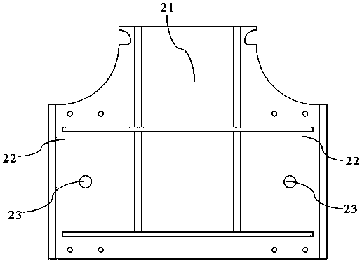
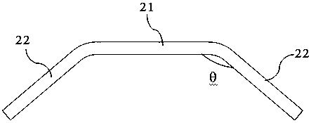
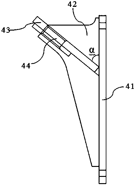
[0024] Such as Figure 1-Figure 10 As shown, the power transmission protection mechanism for rail hanging in this embodiment includes a trolley support 20 and two reduction boxes 30 connected to the trolley 10, and the trolley support 20 is located in the middle of the two reduction boxes 30; 30 is connected with a torsion arm 40, and a buffer de...


PUM


Abstract

The invention discloses a power transmission protection mechanism for a rail crane. The power transmission protection mechanism comprises a trolley support and two reduction gearboxes, wherein the trolley support and the two reduction gearboxes are connected to the trolley, and the trolley support is located in the middle of the two reduction gearboxes; a torsion arm is connected to the reductiongearboxes, and a buffer device is connected between the torsion arm and the trolley support; the trolley support is connected with a protective baffle cover, and the protective baffle cover is buckledon the outer side of the buffer device and is clamped with the torsion arm. The power transmission protection mechanism for the rail crane is stable and reliable, and plays an effective buffering anddamping protection role on the reduction gearboxes. When the rail crane runs at a high speed, the impact force borne by the reduction gearboxes is transmitted to the buffer device through the torsionarm, the buffer device can slow down the impact force, and the buffer device plays a role in buffering and damping. If the buffer device is connected to loosen or break in the running process of therail crane, the protective baffle cover is clamped with the torsion arm, so that a stable connection between the torsion arm and the trolley support is ensured, and the turnover side of the reductiongearboxes is prevented from overturning.

Description

technical field [0001] The invention relates to the technical field of rail cranes, in particular to a power transmission protection mechanism for rail cranes. Background technique [0002] The automatic high-speed rail crane is a loading and unloading equipment applied to the vertical layout of the container automated terminal yard. It mainly interacts with the automatic navigation vehicle and the outer collection truck at both ends of the sea and land sides of the yard. The speed of the cart is as high as 270 m / min. The torque arm system is used to connect the reduction box and the car body of the high-speed rail crane to play the role of fixing, buffering and shock absorption. Compared with the traditional rail crane, the automated high-speed rail crane not only plays the role of loading and unloading, but also undertakes the function of handling. The utilization level of the automatic high-speed rail crane cart mechanism has been greatly increased from T5 to T8. It has h...

Claims


Application Information

Patent Timeline
Patent Type & Authority Applications(China)
IPC IPC(8): B66C9/14B66C9/10F16H57/028F16H57/025
CPCB66C9/10B66C9/14F16H57/025F16H57/028
Inventor 修方强吕向东高荣生谭为宁赵臻王心成秦洪建王国勇栾新刚
Owner QINGDAO PORT INT
Learn More