
Small-size portable dust collecting equipment

A technology of mobile dust removal and equipment, applied in the field of dust removal, can solve the problems of increased pressure, large size of filter bag dust collector, easy damage, etc., and achieve good use effect

Active Publication Date: 2019-08-30
马鞍山科宇环保设备股份有限公司
View PDF19 Cites 0 Cited by
  • Summary
  • Abstract
  • Description
  • Claims
  • Application Information

AI Technical Summary

Problems solved by technology

[0004] However, similar equipment in the prior art has the following deficiencies: first, the filter bag has a low pass rate, high resistance, and consumes a lot of energy, which is not conducive to energy saving and emission reduction; second, as the dust removal time increases, the inner surface of the filter bag will Adsorb a large amount of solid impurities, and the pressure increases, which will lead to a decrease in the ventilation performance of the filter bag and reduce the efficiency of dust removal, which will easily lead to blockage of the filter bag
Although the market has improved it, such as blowing back the surface of the bag through the blowback valve, it is easy to complicate the structure of the filter bag dust collector and easily damage it.
Moreover, in order to accommodate more dust, the size of the filter bag dust collector will be designed larger, and there are also smaller filter bag dust collectors, but this type of dust storage capacity is limited

Method used


Image

  • Small-size portable dust collecting equipment
  • Small-size portable dust collecting equipment
  • Small-size portable dust collecting equipment

Examples


Embodiment 1

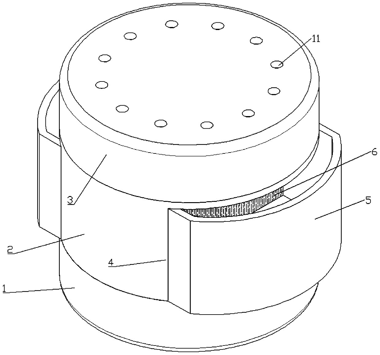
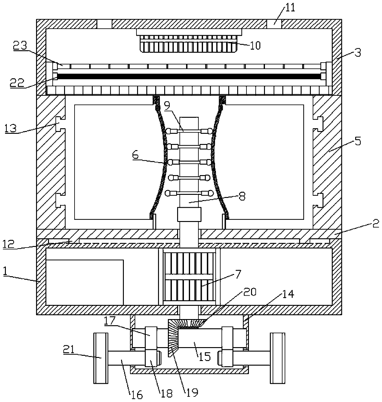
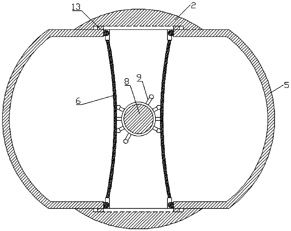
[0028] Embodiment 1, combining Figure 1-4 , a small movable dust removal device, including a bottom shell 1, a middle shell 2 and an upper shell 3, the middle shell 2 and the upper shell 3 are fixed, and the middle shell 2 and the bottom shell 1 are connected in an annular sliding manner, and the left and right sides of the middle shell 2 are arranged There is a notch 4, and a dust storage case 5 is slidingly connected to the left and right in the notch 4. There is an opening above the dust storage case 5, and filter bags 6 are bonded on the opposite surfaces of the left and right dust storage cases 5; There is a double-axis motor 7, the output shaft on the upper side of the double-axis motor 7 passes through the center of the middle shell 2 and is fixed with a connecting rod 8, the outer wall of the connecting rod 8 is sleeved and fixed with a hammer rod 9, and the bottom surface of the bottom shell 1 is fixed There is a driving device, the output shaft below the biaxial mot...


PUM


Abstract

The invention discloses small-size portable dust collecting equipment, and belongs to the field of dust collecting. The equipment comprises a bottom shell, a middle shell and an upper shell, wherein the middle shell is fixed with the upper shell, the middle shell is in annular sliding connection with the bottom shell, the left side and the right side of the middle shell are provided with notches,a dust storage shell is connected in each notch in a left-right sliding manner, an opening is formed above the dust storage shell, and filter bags are bonded on the surfaces opposite to the left duststorage shell and the right dust storage shell; and a double-shaft motor is fixed in the bottom shell, an output shaft at the upper side of the double-shaft motor penetrates through the central part of the middle shell and is fixed with a connecting rod, a hammering rod is sleeved and fixed on the outer side wall of the connecting rod, a driving device is fixed on the bottom surface of the bottomshell, and an output shaft below the double-shaft motor penetrates through the bottom surface of the bottom shell and is connected with the driving device. The small-size portable dust collecting equipment of the invention is provided with a left dust storage shell and a right dust storage shell, so that more dust can be stored; and the equipment can move and rotate simultaneously, and the hammering rod can continuously beat the filter bags on the dust storage shells during rotation, so that the dust cannot be solidified and gathered on the filter bags, and a good using effect is achieved.

Description

technical field [0001] The invention relates to the field of dust removal, in particular to a small movable dust removal device. Background technique [0002] Dust collector is a device that separates dust from flue gas, called dust collector or dust removal equipment. The performance of the dust collector is expressed by the amount of gas that can be handled, the resistance loss when the gas passes through the dust collector, and the dust removal efficiency. At the same time, the price, operation and maintenance costs, service life and difficulty of operation and management of the dust collector are also important factors to consider its performance. Dust collectors are commonly used facilities in boilers and industrial production. [0003] According to the principle of function, dust collectors can be divided into various types, such as dry mechanical dust collectors, wet dust collectors, granular layer dust collectors, electric dust collectors and filter bag dust remova...

Claims


Application Information

Patent Timeline
Patent Type & Authority Applications(China)
IPC IPC(8): B01D46/02B01D46/04B01D46/10B01D46/54
CPCB01D46/02B01D46/04B01D46/10B01D46/543B01D46/62
Inventor 汪茂晓
Owner 马鞍山科宇环保设备股份有限公司
Learn More