Sludge conditioner

A sludge conditioning and component technology, which is applied in sludge treatment, water/sludge/sewage treatment, dehydration/drying/thickened sludge treatment, etc., can solve the problem of reducing the mixing efficiency and impact of sludge and sludge conditioner The service life of the equipment, the inability to achieve continuous work and other problems, to achieve the effect of perfect function, increase speed and reduce pressure

Active Publication Date: 2019-08-30
深圳市鸿卓环保科技有限公司
View PDF9 Cites 4 Cited by
  • Summary
  • Abstract
  • Description
  • Claims
  • Application Information

AI Technical Summary

Problems solved by technology

[0004] Although the above-mentioned patent can realize automatic mixing of sludge and sludge conditioner, there are following deficiencies in actual use. First, the device needs to mix sludge and sludge conditioner in batches, each Quantitative work is required every time. During work, other sludge cannot continue to enter the equipment, and continuous work cannot be achieved, thereby reducing the mixing efficiency of sludge and sludge conditioner. Second, due to the high density of sludge, it will Increase the difficulty of stirring, and when the above-mentioned device is in use, it directly uses the motor to drive the stirring rod to stir the sludge, which is more difficult to work and increases the load of the motor, which will affect the service life of the equipment

Method used


Image

  • Sludge conditioner
  • Sludge conditioner
  • Sludge conditioner

Examples


Embodiment Construction

[0029] In order to make the object, technical solution and advantages of the present invention clearer, the present invention will be further described in detail below in conjunction with the accompanying drawings and embodiments. It should be understood that the specific embodiments described here are only used to explain the present invention, not to limit the present invention.

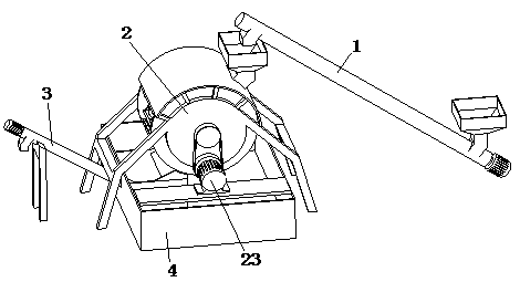
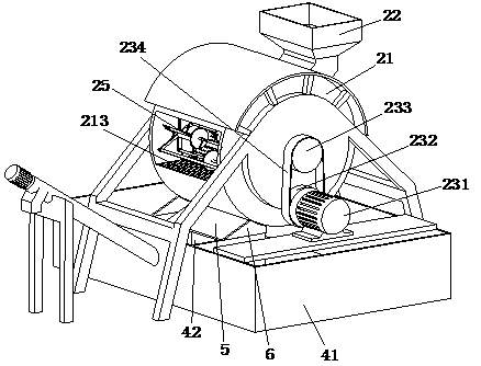
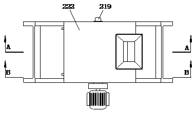
[0030] refer to Figure 1 to Figure 7It can be seen that a sludge conditioning device includes a feed screw conveyor 1, a transport mechanism 2 and a discharge screw conveyor 3, and the transport mechanism 2 includes a drive assembly 23, a feed assembly 22, a transport assembly 21, and a transmission assembly 24 and several agitating assemblies 25, the driving assembly 23 is installed on one side of the transport assembly 21 and is connected by transmission between the two, the feeding assembly 22 is arranged on the upper end of the transportation assembly 21, and the transmission assembly 24 is ar...


PUM


Abstract

The invention relates to the field of sludge treatment equipment and particularly relates to a sludge conditioner. The sludge conditioner includes a feeding spiral conveyor, a conveying mechanism anda discharging spiral conveyor. The conveying mechanism includes a driving component, a feeding component, a conveying component, a transmitting component and a plurality of stirring components. The driving component is arranged on one side of the conveying component and the two are in transmission connection. The feeding component is arranged on an upper end of the conveying component. The transmitting component is arranged on the other end of the conveying component. The plurality of stirring components are circumferentially distributed in the conveying component. Each stirring component is in transmission connection with the conveying component through the transmitting component. A holding component is arranged right below the conveying component. When in use, the sludge conditioner disclosed by the invention can work continuously, thus improving conditioning efficiency of sludge. And during a conditioning process, separated sludge can be filtered out, reducing work amount during subsequent dewatering work. The sludge conditioner of the invention can also reduce labor intensity of equipment, prolonging the service life thereof.

Description

technical field [0001] The invention relates to the field of sludge treatment equipment, in particular to a sludge conditioning device. Background technique [0002] A large amount of sludge will be produced in industrial production and sewage treatment, and these sludges will contain a large amount of water and organic matter. In order to improve the utilization rate of resources and reduce the impact of sludge on the environment, it is necessary to conduct in-depth sludge Dewatering, so that the water content of the sludge is less than 60%. In order to improve the dehydration performance of sludge, the sludge must be treated in the early stage, which is what we call "sludge conditioning".  The sludge is tempered before sludge dehydration to change the physical and chemical properties of sludge particles, destroy its colloidal structure, and reduce its affinity with water, thereby improving the dehydration performance of sludge. A commonly used method for sludge conditioni...

Claims


Application Information

Patent Timeline
Patent Type & Authority Applications(China)
IPC IPC(8): C02F11/14C02F11/121B01F9/00
CPCC02F11/14C02F11/121B01F29/30B01F29/40352B01F29/4031B01F29/4022
Inventor 王子腾
Owner 深圳市鸿卓环保科技有限公司
Why Eureka
Try Eureka