
Liquid crystal display device

A technology for liquid crystal display devices and display panels, which is applied in nonlinear optics, instruments, optics, etc., can solve problems such as the inability to meet the requirements for narrow bezels, and achieve the effect of meeting the design requirements for narrow bezels and preventing optical defects

Pending Publication Date: 2019-08-30
WUHAN CHINA STAR OPTOELECTRONICS TECH CO LTD
View PDF0 Cites 3 Cited by
  • Summary
  • Abstract
  • Description
  • Claims
  • Application Information

AI Technical Summary

Problems solved by technology

[0004] The invention provides a liquid crystal display device to solve the technical problem that in the existing liquid crystal display device, the back frame and the touch screen are generally fixed by using a middle rubber frame structure on the side of the back frame, which leads to the technical problem that the narrow frame cannot be met.

Method used


Image

  • Liquid crystal display device
  • Liquid crystal display device
  • Liquid crystal display device

Examples


Embodiment Construction

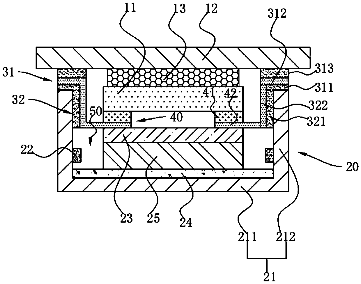
[0030] The following descriptions of the various embodiments refer to the accompanying drawings to illustrate specific embodiments in which the invention may be practiced. The directional terms mentioned in the present invention, such as [top], [bottom], [front], [back], [left], [right], [inside], [outside], [side], etc., are only for reference The orientation of the attached schema. Therefore, the directional terms used are used to illustrate and understand the present invention, but not to limit the present invention. In the figures, structurally similar elements are denoted by the same reference numerals.

[0031] The present invention aims at the technical problem that in the existing liquid crystal display device, a middle rubber frame structure is generally adopted on the side of the back frame to fix the back frame and the touch screen, which leads to the technical problem that the requirement for a narrow frame cannot be met. The present invention can solve the above...


PUM


Abstract

The invention provides a liquid crystal display device. The device comprises a display panel, a backlight module and a connecting part for connecting the backlight module and the display panel; wherein the backlight module comprises a back frame, and the back frame comprises a back plate and a bending part fixedly connected with the back plate; wherein the connecting part comprises a first fixingpart positioned on the end face of the bending part, the first fixing part is fixedly connected with the end face of the bending part and the display panel, and the orthographic projection of the endface of the bending part on the display panel comprises the orthographic projection of the outer side of the first fixing part on the display panel. The connecting part replaces a middle rubber framestructure in the conventional design, and on the premise of ensuring the connection strength and the vehicle-mounted reliability of a back frame module and the display panel, the thickness of one member is reduced in the expansion direction of an optical film, thereby meeting the design requirement of narrow frame of the liquid crystal display device, and meanwhile, enough space can be reserved between the optical film and the inner side wall of the bending part, the optical film is prevented from being wrinkled due to expansion obstruction to cause optical failure.

Description

technical field [0001] The invention relates to the field of display technology, in particular to a liquid crystal display device. Background technique [0002] With the development of vehicle display technology, the requirements for vehicle display panels are getting higher and higher. Under high temperature conditions, the optical film in the vehicle display panel will expand, and the industry's requirements for the frame of the vehicle display panel are getting narrower and narrower. If there is not enough space reserved in the direction of film expansion, the film will be damaged. Optical defects due to diaphragm wrinkling due to hindered expansion. [0003] Due to the high reliability requirements of the on-board display, a sufficient gap needs to be reserved between the optical film and the back frame to ensure that the expansion of the optical film will not be hindered under high temperature conditions. For medium and large-sized car display panels, considering the s...

Claims


Application Information

Patent Timeline
IPC IPC(8): G02F1/1333G02F1/13357
CPCG02F1/133308G02F1/13338G02F1/133615G02F1/133314
Inventor 周政
Owner WUHAN CHINA STAR OPTOELECTRONICS TECH CO LTD
Features
  • Generate Ideas
  • Intellectual Property
  • Life Sciences
  • Materials
  • Tech Scout
  • Unparalleled Data Quality
  • Higher Quality Content
  • 60% Fewer Hallucinations
Learn More