Switch cabinet and its valve linkage system

A linkage system and switchgear technology, which is applied in the direction of pull-out switchgear, switchgear, electrical components, etc., can solve the problem that the upper valve and the lower valve cannot accurately realize synchronous movement, and achieve convenient design and installation, and simple transmission connection structure Effect

Active Publication Date: 2020-10-13
PINGGAO GRP +1
View PDF8 Cites 0 Cited by
  • Summary
  • Abstract
  • Description
  • Claims
  • Application Information

AI Technical Summary

Problems solved by technology

[0005] The purpose of the present invention is to provide a valve linkage system to solve the problem in the prior art that the upper valve and the lower valve drive system respectively drive the opening and closing of the valves, resulting in the inability of the upper valve and the lower valve to accurately realize the synchronous movement; the present invention The purpose is also to provide a switchgear that solves the above problems

Method used


Image

  • Switch cabinet and its valve linkage system
  • Switch cabinet and its valve linkage system
  • Switch cabinet and its valve linkage system

Examples


specific Embodiment 2

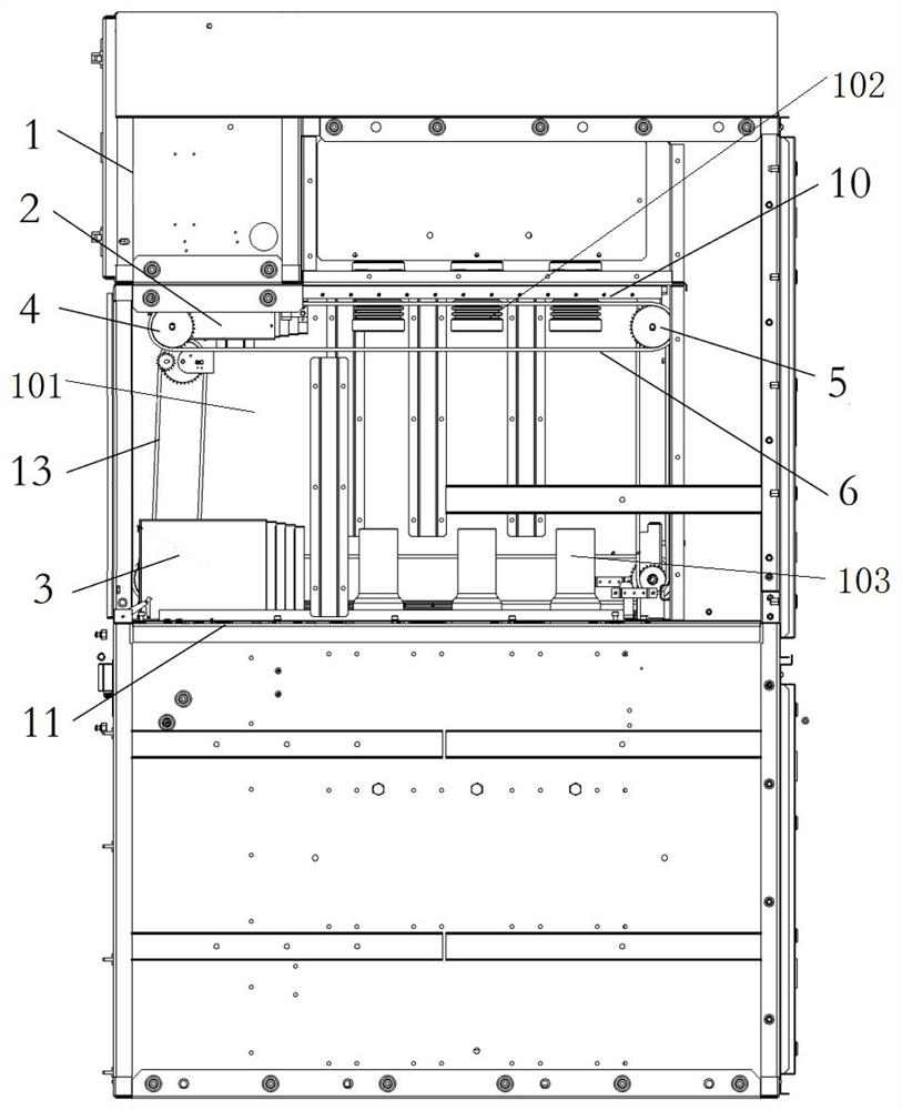
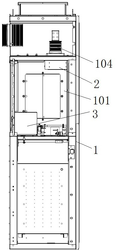
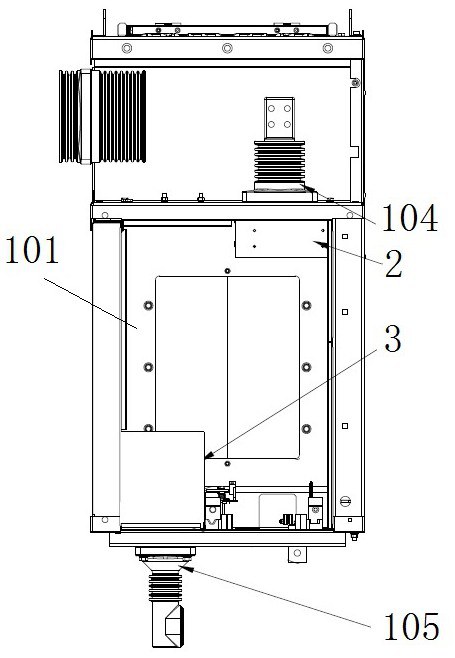
[0048] Specific embodiment 2 of the switchgear of the present invention, the switchgear includes a cabinet body and a circuit breaker room arranged in the cabinet body, the valve linkage system is arranged in the circuit breaker room, and the valve linkage system includes The upper valve device and the lower valve device, the upper valve device and the lower valve device both include a telescopic valve structure, and a synchronous transmission mechanism is provided between the two valve devices to drive the synchronous telescopic action of the two telescopic valve structures. The synchronous telescopic action of the upper valve device and the lower valve device is driven by the synchronous transmission mechanism, which realizes the synchronous movement of the upper valve and the lower valve, and solves the problem in the prior art that the upper valve and the lower valve drive system drive the valve to open and close separately. The problem that the upper valve and the lower va...

specific Embodiment 8

[0054] The specific embodiment 8 of the switchgear of the present invention, as a further optimization of any one of the specific embodiments 2 to 6 of the switchgear of the present invention, considering that the opening of the valve by misoperation will affect the personal safety of maintenance personnel, this embodiment The valve linkage system in the valve also includes an interlock device that restricts the action of the upper valve device and the lower valve device in the closed state.

[0055] The specific embodiment of the valve linkage system of the present invention, the structure of the valve linkage system in this embodiment is the same as the valve linkage system described in any one of the specific embodiments 1 to 8 of the above-mentioned switchgear, and will not be described again.


PUM


Abstract

The invention relates to a switch cabinet and a valve linkage system thereof. The valve linkage system comprises an upper valve device and a lower valve device which are arranged in the up-down direction of the switch cabinet, each of the upper valve device and the lower valve device comprises a telescopic valve structure, and a synchronous transmission mechanism for driving the two telescopic valve structures to synchronously stretch out and retract is arranged between the two valve devices. The upper valve device and the lower valve device are driven by the synchronous transmission mechanismto synchronously stretch and retract, synchronous movement of the upper valve and the lower valve is achieved, and the problem that in the prior art, an upper valve driving system and a lower valve driving system are adopted for driving the valves to be opened and closed respectively so that the upper valve and the lower valve cannot accurately achieve synchronous movement is solved.

Description

technical field [0001] The invention relates to a switch cabinet and a valve linkage system thereof. Background technique [0002] At present, there are many types of switch products produced and applied in the market at home and abroad. The general structure type is front, middle, rear and left, middle, and right arrangements. When the products arranged in the front, middle and rear are fixed, the compartment The division is not obvious, the continuity of operation is lost and the protection level is low; while the three-phase arrangement arranged on the left, middle and right is mostly a removable metal-enclosed switchgear, which needs a valve to open and close the charged body. Hanging plate, lower hanging plate, left and right driving crank arms, connecting rod, guide rod and other components. The crank arms on both sides are driven by the rocking in and out of the chassis, and the crank arms drive the pull rod to move to realize the opening and closing of the valve, an...

Claims


Application Information

Patent Timeline
Patent Type & Authority Patents(China)
IPC IPC(8): H02B11/133H02B11/167
CPCH02B11/133H02B11/167
Inventor 张永辉李小军袁端磊卢健冯祥伟费翔朱志豪王海燕杨芳耿晓璐
Owner PINGGAO GRP
Why Eureka
Try Eureka