A new energy transmission system and crushing system

A conveying system and new energy technology, applied in the direction of transportation and packaging, conveyor objects, grain processing, etc., can solve the problems of single structure, limited use, large power consumption, etc., and achieve the effect of ensuring effective transportation and promoting development

Active Publication Date: 2020-05-01
HUNAN MECHANICAL & ELECTRICAL POLYTECHNIC
View PDF5 Cites 0 Cited by
  • Summary
  • Abstract
  • Description
  • Claims
  • Application Information

AI Technical Summary

Problems solved by technology

The existing transmission system has a single structure and its use is limited, and the existing transmission system generally uses electric energy as the power source, which consumes a lot of power. It is limited for places where the electric equipment is limited or cannot be used, so the transmission system needs to further develop new energy sources , to promote the development of conveying systems to meet the needs of different use cases

Method used


Image

  • A new energy transmission system and crushing system
  • A new energy transmission system and crushing system
  • A new energy transmission system and crushing system

Examples


Embodiment 1

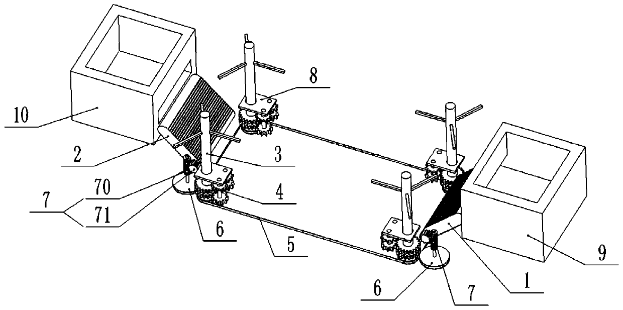
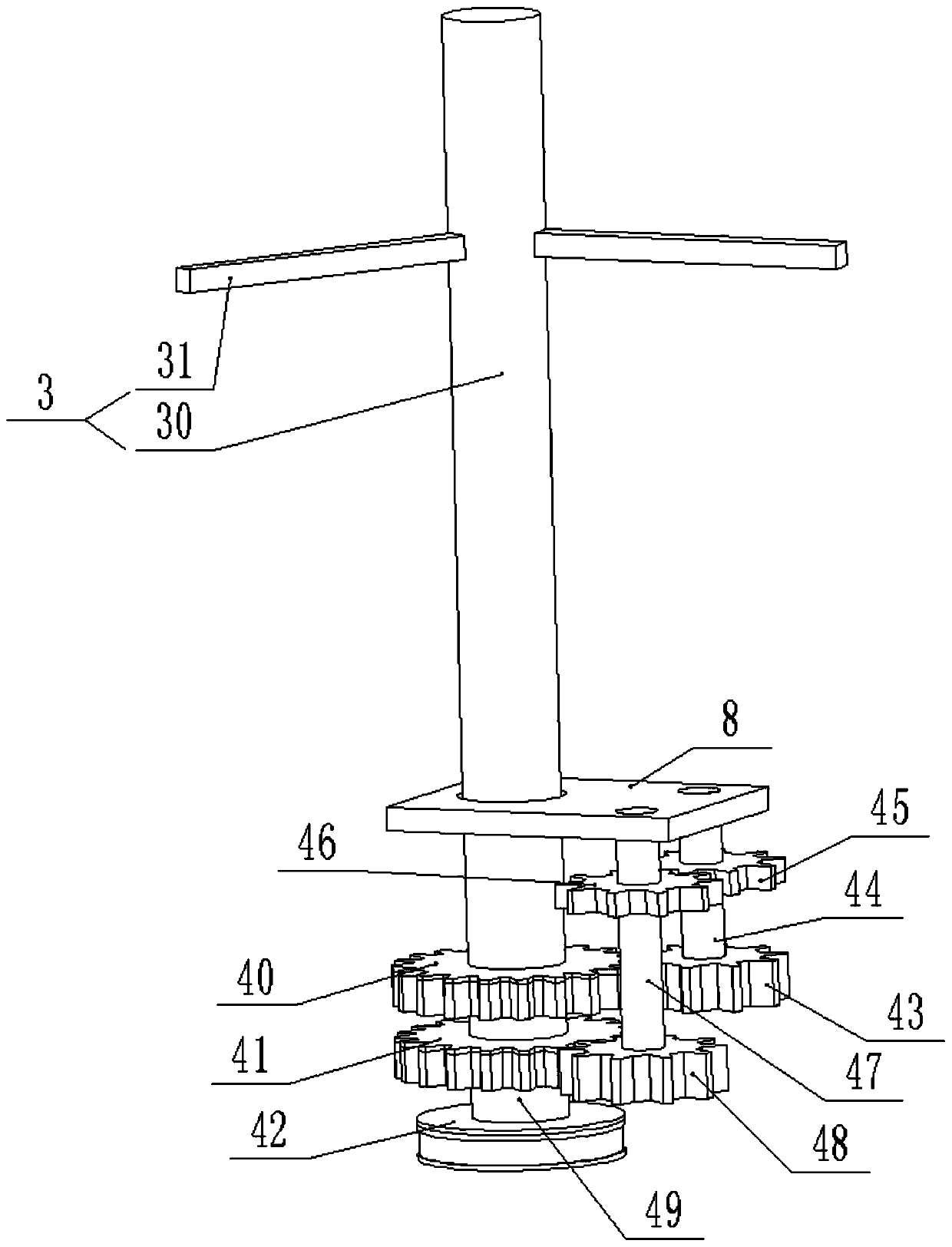
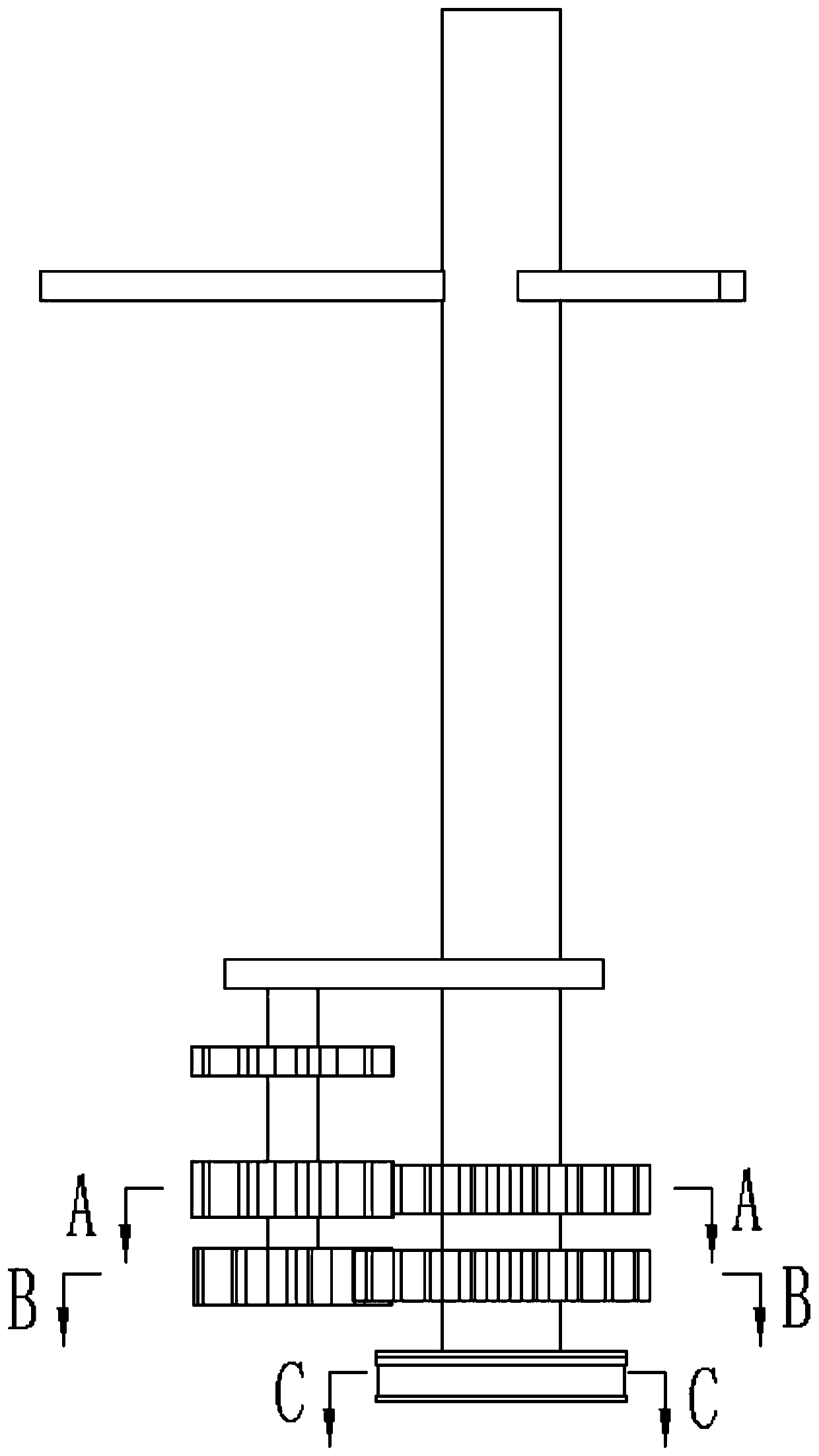
[0032] Such as Figure 1-6As shown, a new energy delivery system provided by this embodiment includes a power mechanism and a delivery mechanism; the delivery mechanism includes a first delivery assembly 1 and a second delivery assembly 2; the power mechanism includes a drive assembly 3, a one-way Transmission assembly 4, conveyor belt 5, driven pulley 6 and worm gear mechanism 7; described one-way transmission assembly 4 comprises first one-way gear 40, second one-way gear 41, first transmission gear 43, second transmission Gear 45, the third transmission gear 46, the fourth transmission gear 48, the first transmission shaft 44, the second transmission shaft 47 and the one-way driving pulley 42; the first one-way gear 40 and the second one-way gear 41 alternate Installed on the drive assembly 3; the second one-way gear 41 is connected with a drive shaft 49, specifically, the second one-way gear 41 is integrated with the drive shaft 49; the one-way driving belt The wheel 42 i...

Embodiment 2

[0047] Such as Figure 1-9 As shown, a crushing system provided in this embodiment includes the new energy transmission system described in Embodiment 1, and also includes a crushing mechanism 11 and a vibration mechanism 12; the crushing mechanism 11 is located between the first conveying assembly 1 and the second Between the two conveying components 2.

[0048] The crushing mechanism 11 includes a base plate 102, a top plate 101 disposed on the base plate 102, and a crushing pedal 103 disposed on the top plate 101; a delivery space is provided between the base plate 102 and the top plate 101; the crushing The pedal 103 can move up and down relative to the top plate 101;

[0049] The vibration mechanism 12 includes a connecting rod 122, a supporting plate 121 and a vibration feeding pedal 120; the connecting rod 122 and the supporting plate 121 are respectively connected with the bottom plate 102 and the top plate 101; the vibration feeding pedal 120 is installed on the on ...


PUM


Abstract

The invention discloses a new energy delivery system, which includes a power mechanism and a delivery mechanism; the delivery mechanism includes a first delivery assembly and a second delivery assembly; Drive pulley and worm and worm gear mechanism; the one-way transmission assembly includes the first one-way gear, the second one-way gear, the first transmission gear, the second transmission gear, the third transmission gear, the fourth transmission gear, the first transmission gear shaft, second transmission shaft and one-way drive pulley. The present invention also provides a crushing system, including the new energy transmission system, and also includes a crushing mechanism and a vibration mechanism. The invention has flexible structural design, convenient use, energy saving and environmental protection, and improves production efficiency.

Description

technical field [0001] The invention relates to a new energy transmission system and a crushing system. Background technique [0002] The existing conveying system has the advantages of high degree of automation, convenient use, and greatly improved production efficiency, so it is widely used in various fields. The existing transmission system has a single structure and its use is limited, and the existing transmission system generally uses electric energy as the power source, which consumes a lot of power. It is limited for places where the electric equipment is limited or cannot be used, so the transmission system needs to further develop new energy sources , to promote the development of conveying systems to meet the needs of different usage situations. Contents of the invention [0003] The purpose of the present invention is to overcome the deficiencies of the prior art and provide a new energy delivery system with flexible structural design, convenient use, energy s...

Claims


Application Information

Patent Timeline
Patent Type & Authority Patents(China)
IPC IPC(8): B65G47/52B02C21/00
CPCB02C21/00B65G47/52
Inventor 庹前进刘敏
Owner HUNAN MECHANICAL & ELECTRICAL POLYTECHNIC
Why Eureka
Try Eureka