
Elevator for automobile overhaul

A technology for lifts and automobiles, which is applied to lifting frames, lifting devices, etc., and can solve the problems of difficulty in viewing at the same time, needing to work with the head up, and leaving the vehicle.

Pending Publication Date: 2019-09-03
SHENZHEN POLYTECHNIC
View PDF0 Cites 6 Cited by
  • Summary
  • Abstract
  • Description
  • Claims
  • Application Information

AI Technical Summary

Problems solved by technology

[0002] Cars often need to be lifted during inspection and maintenance, so that the chassis of the car can be inspected and maintained. At present, cars are lifted by a gantry lift. There is a lifting block, which is driven up and down by a hydraulic cylinder or a motor, and two support arms are hinged on the lifting block, both of which can swing below the bottom beam of the vehicle to lift the vehicle. After the lift is lifted, since the support arm is only held down by the weight of the vehicle, there is a risk of detaching from the vehicle under the action of an external force. In addition, the lift cannot adjust the inclination angle of the chassis of the car relative to the ground. Maintenance workers overhaul the car It is difficult to observe the entire chassis of the car at the same time, which brings inconvenience to the maintenance workers.

Method used


Image

  • Elevator for automobile overhaul
  • Elevator for automobile overhaul
  • Elevator for automobile overhaul

Examples


Embodiment Construction

[0030] The following will clearly and completely describe the technical solutions in the embodiments of the present invention with reference to the accompanying drawings in the embodiments of the present invention. Obviously, the described embodiments are only some, not all, embodiments of the present invention. Based on the embodiments of the present invention, all other embodiments obtained by persons of ordinary skill in the art without making creative efforts belong to the protection scope of the present invention.

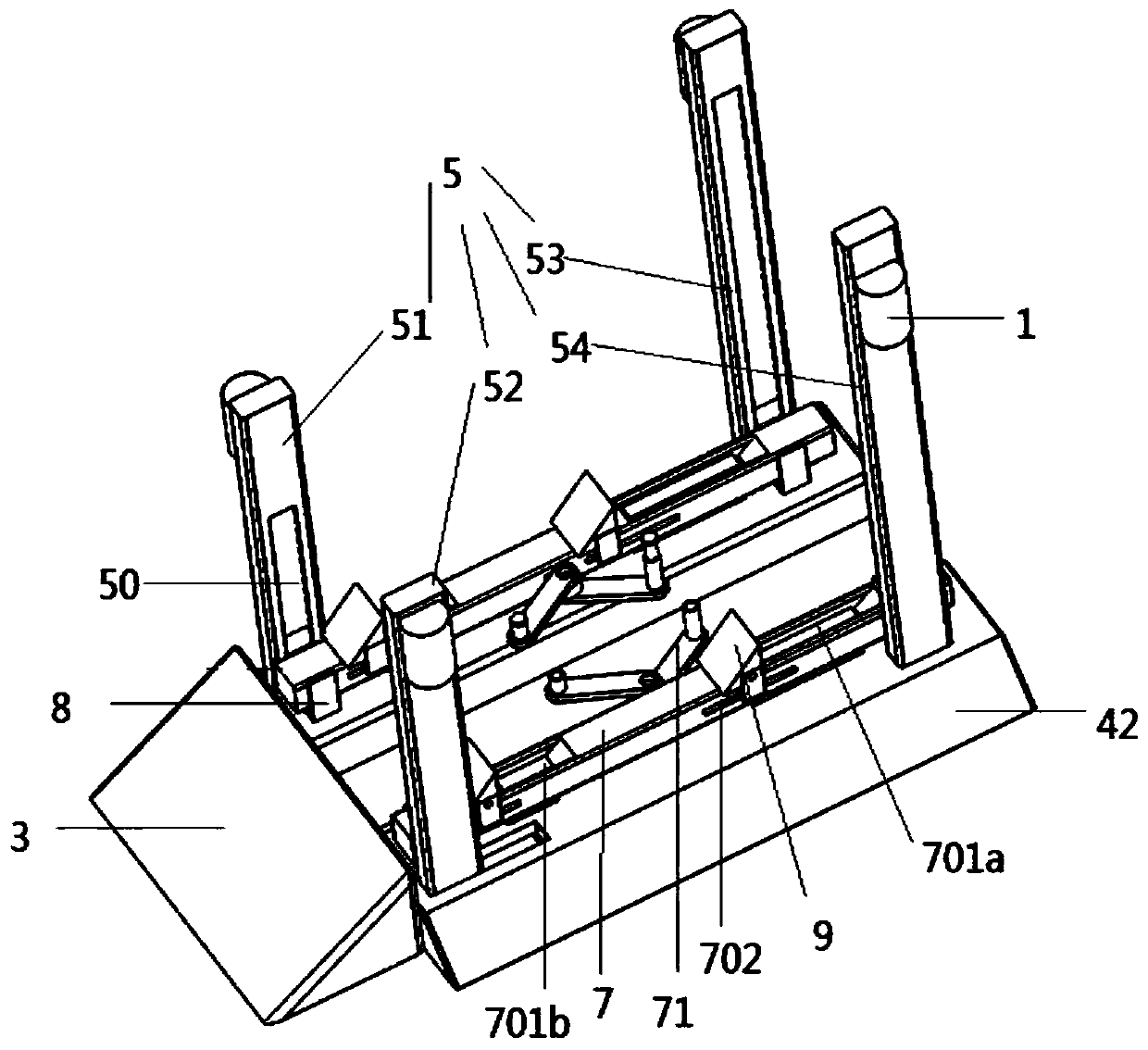
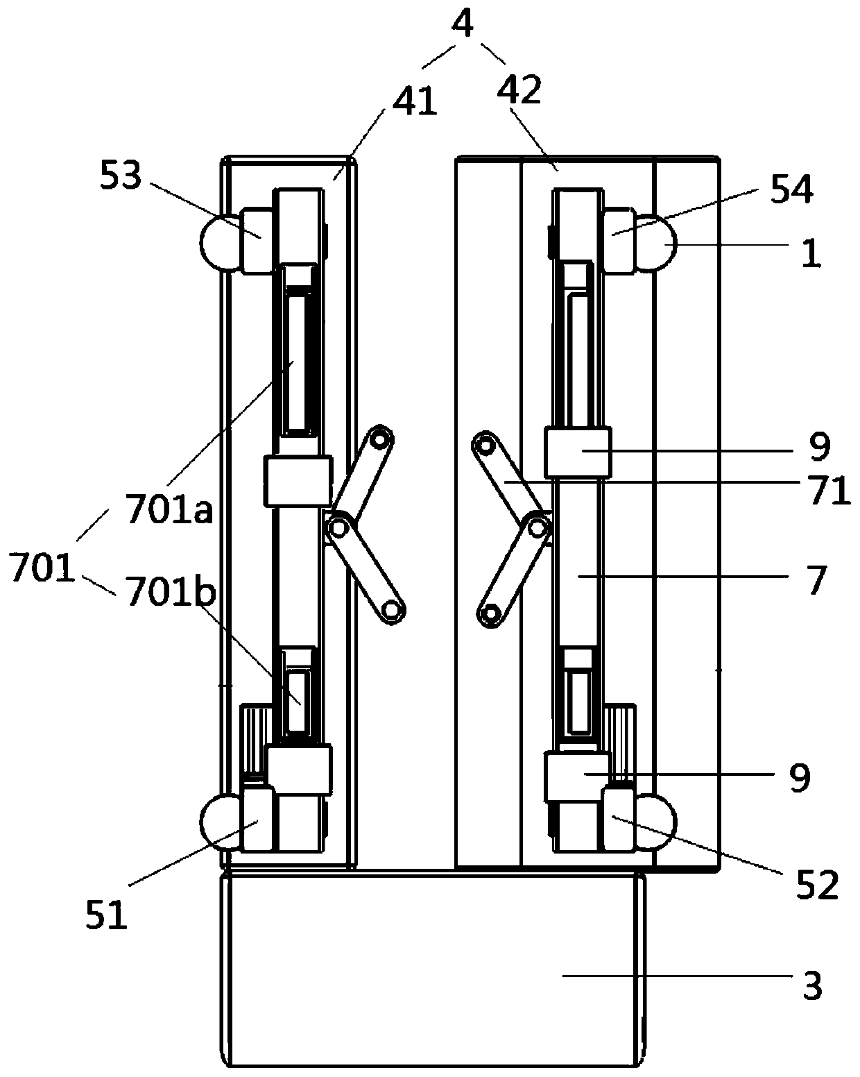
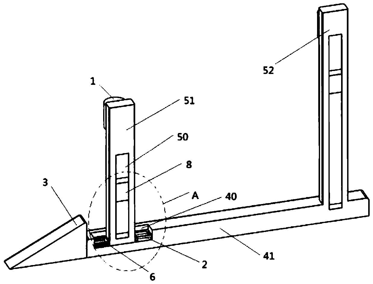
[0031] See attached figure 1 - attached Figure 9 , a car lift for maintenance, including a motor 1, a cylinder 2 and an inclined seat plate 3, also includes a base part 4, a column 5, spring pressure block 6, lifting column 7, lifting block 8 and wheel stopper 9; base Part 4 includes a first base 41 and a second base 42, both of which are in contact with the ground to ensure the stable operation of the elevator as a whole; the first base 41 is fixedly connec...


PUM


Abstract

The invention provides an elevator for automobile overhaul. The elevator for automobile overhaul comprises motors, cylinders and an oblique base plate and further comprises a base portion, vertical columns, elastic blocks, lifting columns, lifting blocks and wheel displacement restrictors. The base portion is in contact with the ground and fixedly connected with the oblique base plate so that integral stable operation of the elevator can be guaranteed. Moving grooves are also formed in the base portion, the vertical columns are vertically arranged above the base portion and connected with themoving grooves in a clamped manner, and the vertical columns are driven by the cylinders to move back and forth in the moving grooves. The lifting blocks are driven by the motors so that the lifting blocks can move up and down along the vertical columns. The lifting columns are rotatably connected with the lifting blocks and move together with the lifting blocks. The lifting columns are provided with supporting arms which are connected with the lifting columns in a hinged manner. The wheel displacement restrictors are arranged on the lifting columns in a manner that the wheel displacement restrictors can slide on the lifting columns. The lifting columns, the cylinders, the vertical columns and the motors are used cooperatively; after an automobile is elevated, the oblique angle of the automobile can be adjusted, and convenience is brought to the maintenance staff; and by means of wheel grooves, the supporting arms and the wheel displacement restrictors, when the lifting columns incline, the automobile can be better fixed, and the automobile is prevented from slipping backwards.

Description

technical field [0001] The invention belongs to the technical field of automobile maintenance equipment, and relates to a lift for automobile maintenance. Background technique [0002] Cars often need to be lifted during inspection and maintenance, so that the chassis of the car can be inspected and maintained. At present, cars are lifted by a gantry lift. There is a lifting block, which is driven up and down by a hydraulic cylinder or a motor, and two support arms are hinged on the lifting block, both of which can swing below the bottom beam of the vehicle to lift the vehicle. After the lift is lifted, because the support arm is only held down by the weight of the vehicle, there is a risk of detaching from the vehicle under the action of an external force. In addition, the lift cannot adjust the inclination angle of the car chassis relative to the ground. Maintenance workers overhaul the car When working with the head up, it is difficult to observe the entire chassis of th...

Claims


Application Information

Patent Timeline
IPC IPC(8): B66F7/00B66F7/28
CPCB66F7/00B66F7/28
Inventor 王品
Owner SHENZHEN POLYTECHNIC
Learn More