
Veneer groove wheel bending mechanism

A technology of bending mechanism and grooved wheel, applied in the field of single-plate grooved wheel bending mechanism, can solve the problems of high space position and cost, inconvenient mechanism assembly and maintenance, and complicated workpieces, so as to reduce production costs, reduce production processes, The effect of improving productivity

Inactive Publication Date: 2019-09-06
温州瑞孚自动化科技有限公司
View PDF0 Cites 0 Cited by
  • Summary
  • Abstract
  • Description
  • Claims
  • Application Information

AI Technical Summary

Problems solved by technology

[0003] Existing PIN pin bending mechanisms include servo bending and air cylinder specified position bending, but these two bending mechanisms are expensive and inconvenient for mechanism assembly and maintenance operations
Servo bending is servo rotary bending. The rotation angle is controlled by a servo motor. The mechanism is relatively stable, but the workpiece is more complicated; the bending at the designated position of the cylinder means that the inclination angle of the installation position of the cylinder and the bending angle of the PIN needle are in a certain order. The space position and cost required by the bend are relatively high
In the electronic component bending equipment in the prior art, after the bending process is completed, after the bending block used for bending the electronic component terminal rises and resets, the PIN pin of the plastic part will rebound to a certain extent, resulting in The terminals of electronic components do not reach the specified bending angle

Method used


Image

  • Veneer groove wheel bending mechanism
  • Veneer groove wheel bending mechanism
  • Veneer groove wheel bending mechanism

Examples


Embodiment Construction

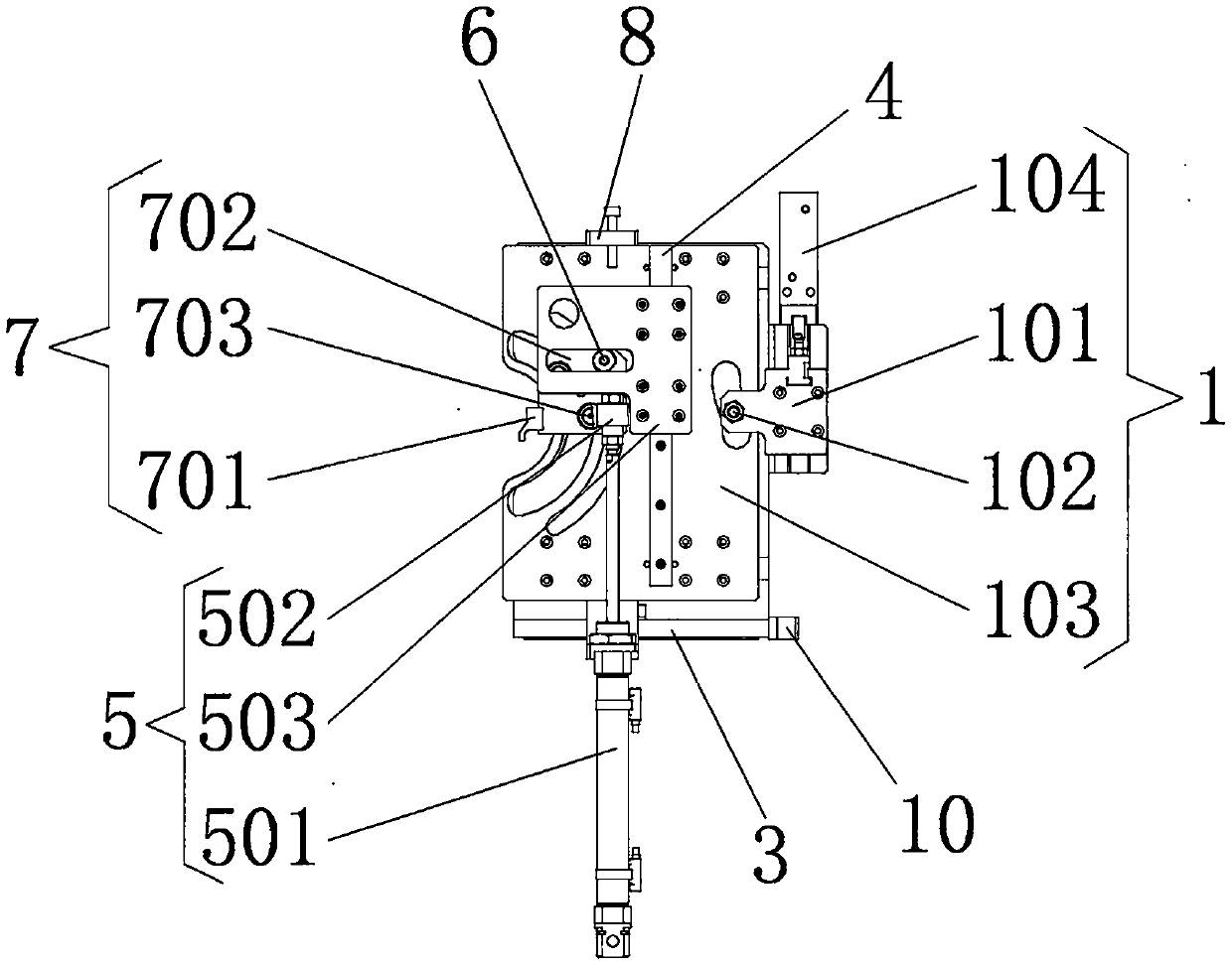
[0023] The following will clearly and completely describe the technical solutions in the embodiments of the present invention with reference to the accompanying drawings in the embodiments of the present invention. Obviously, the described embodiments are only some, not all, embodiments of the present invention.

[0024] In describing the present invention, it should be understood that the terms "upper", "lower", "front", "rear", "left", "right", "top", "bottom", "inner", " The orientation or positional relationship indicated by "outside", etc. is based on the orientation or positional relationship shown in the drawings, and is only for the convenience of describing the present invention and simplifying the description, rather than indicating or implying that the referred device or element must have a specific orientation, so as to Specific orientation configurations and operations, therefore, are not to be construed as limitations on the invention.

[0025] refer to Figure ...


PUM


Abstract

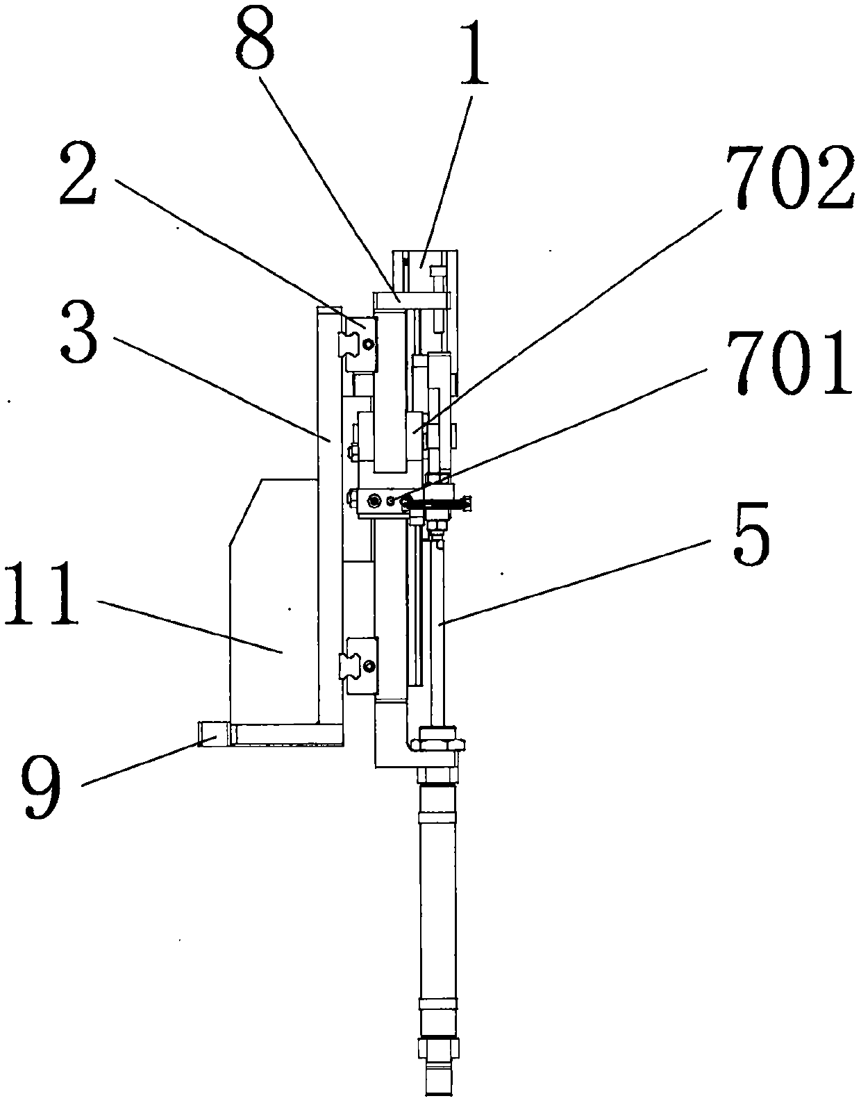
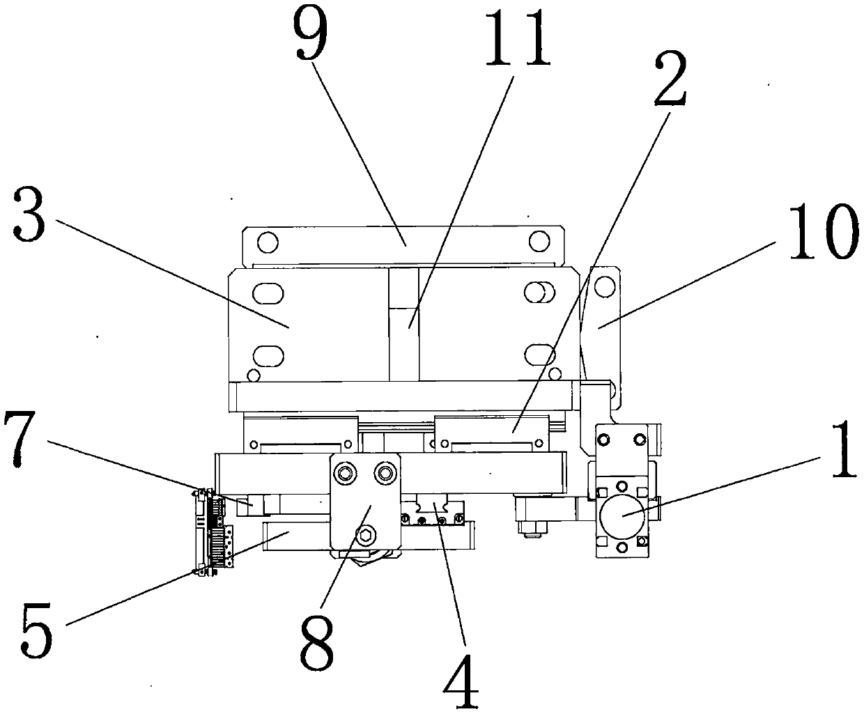
The invention relates to the technical field of plastic part contact pin bending, and discloses a veneer groove wheel bending mechanism. The veneer groove wheel bending mechanism comprises an inclinedwedge mechanism; the back surface of the inclined wedge mechanism is fixedly connected with a first line rail; the inner wall of the first line rail is slidingly connected with a line rail fixed plate; the front surface of the inclined wedge mechanism is fixedly connected with a second line rail; the surface of the second line rail is slidingly connected with a shifting mechanism; the surface ofthe shifting mechanism is fixedly connected with the bottom of the inclined wedge mechanism through a fixed frame; and a rotating shaft is fixedly connected to the front surface of the inclined wedgemechanism. The veneer groove wheel bending mechanism is provided with the shifting mechanism and a bending device, and meanwhile, is provided with the inclined wedge mechanism capable of performing trajectory motion bending on pins and first and second cam rollers, so that the displacements in X, Y and Z directions are all adjustable to meet the bending of the pins in different space positions. For multi-pin-position bending of the same types of products or complex plastic parts, the veneer groove wheel bending mechanism can be applied to different types of bending machines.

Description

technical field [0001] The invention relates to the technical field of bending processing of pins of plastic parts, in particular to a single-plate sheave bending mechanism. Background technique [0002] For plastic parts that need to be bent, especially various electronic connectors, the molding is usually achieved by assembling the plastic parts with multiple metal PIN pins, and the PIN pins in the plastic parts are bent by the bending device, and the PIN pins The assembly method with plastic parts is generally plug-in or injection molding. The PIN pin bending refers to bending multiple PIN pins in the plastic part according to the specified position and angle, so as to meet the customer's purpose and requirements. [0003] Existing PIN pin bending mechanisms include servo bending and air cylinder specified position bending, but these two bending mechanisms are expensive and inconvenient for mechanism assembly and maintenance operations. Servo bending is servo rotary ben...

Claims


Application Information

Patent Timeline
Patent Type & Authority Applications(China)
IPC IPC(8): B21F1/00
CPCB21F1/00
Inventor 周建国林贤董薛洋龙
Owner 温州瑞孚自动化科技有限公司
Learn More