Stamping die

A stamping die and die base technology, applied in the field of dies, can solve problems such as wasting resources and increasing production costs, and achieve the effect of saving resources and reducing production costs

Active Publication Date: 2019-09-10
佛山市顺德区方智五金电器有限公司
View PDF6 Cites 2 Cited by
  • Summary
  • Abstract
  • Description
  • Claims
  • Application Information

AI Technical Summary

Problems solved by technology

However, the traditional stamping die has the following disadvantages: multiple sets of dies are developed separately for convex hulls of different depths, which wastes resources and increases production costs

Method used


Image

  • Stamping die
  • Stamping die
  • Stamping die

Examples


Embodiment Construction

[0022] Embodiments of the present invention will be described below with reference to the accompanying drawings. During this process, in order to ensure the clarity and convenience of the description, we may exaggerate the width of the lines or the size of the components in the illustrations.

[0023] In addition, the following terms are defined based on the functions in the present invention, and may be different depending on the user, the operator's intention, or convention. Therefore, these terms are defined based on the entire content of this specification.

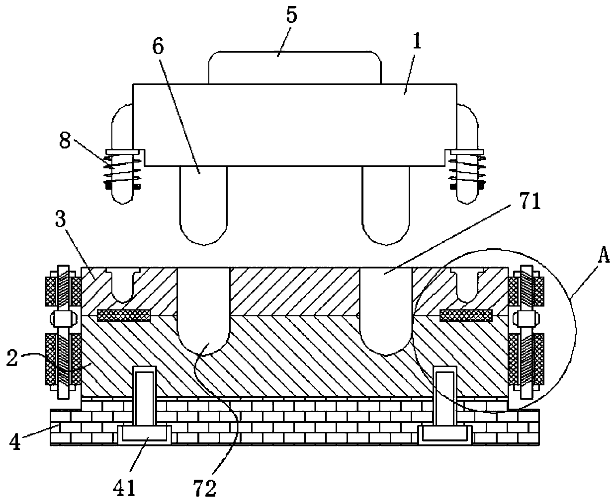
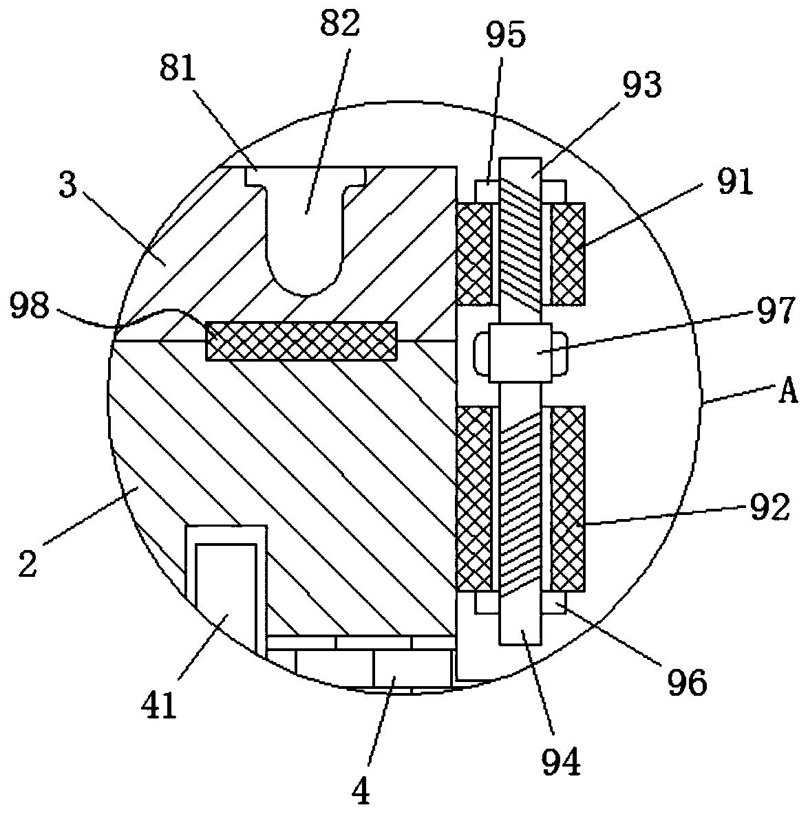
[0024] like Figure 1-4 As shown, a stamping die includes an upper die base 1 and a lower die base 4, the upper die base 1 is located at a position just above the lower die base 4, and a connecting base 5 is provided at the central position of the top surface of the upper die base 1, The top of the connecting seat 5 is provided with rounded corners on both sides, the top of the connecting seat 5 is connected to the ...


PUM


Abstract

The invention relates to a stamping die which comprises an upper die holder and a lower die holder, wherein the upper die holder is positioned right above the lower die holder; a punch is arranged onthe bottom surface of the upper die holder; a lower die plate is arranged at the top end of the lower die holder; a base plate is arranged on the top surface of the lower die plate; connecting mechanisms are uniformly arranged between the base plate and the lower die plate; a guiding buffer mechanism is arranged between the upper die holder and the base plate; a die cavity is formed in the top surface of the lower die plate; a through hole is formed in the base plate and communicates with the die cavity; each of the connecting mechanisms comprises an upper connecting block; and the upper connecting blocks are uniformly arranged in the circumferential direction of the base plate. According to the stamping die, the base plate with the corresponding thickness is changed according to the demands of convex hulls with different depths, then, the base plate is mounted on the lower die plate through the connecting mechanisms, and a set of die does not need to be developed separately for the convex hulls with different depths, so that the resource is saved and the production cost is reduced.

Description

technical field [0001] The invention relates to the technical field of molds, in particular to a stamping mold. Background technique [0002] A mold is a mold and tool for forming a product. This tool is composed of various parts, and the shape of the product is obtained mainly by changing the physical state of the material being formed. In industrial production, it is often used for injection molding, blow molding, and forging. The mold is divided into plastic mold, stamping mold and so on. Among them, stamping dies are widely used for stamping metal parts. [0003] In the actual production process of metal stamping parts, convex hulls of different depths are often punched out according to the needs of customers. However, traditional stamping dies have the following disadvantages: multiple sets of dies are separately developed for convex hulls of different depths, which wastes resources and increases production costs. To this end, we designed a stamping die, which can m...

Claims


Application Information

Patent Timeline
Patent Type & Authority Applications(China)
IPC IPC(8): B21D37/10
CPCB21D37/10
Inventor 徐承朱乐乐邹帅虎
Owner 佛山市顺德区方智五金电器有限公司
Why Eureka
Try Eureka