
Underwater light with diffuser

Inactive Publication Date: 2008-06-05
UNDERWATER LIGHTS USA
View PDF58 Cites 120 Cited by
  • Summary
  • Abstract
  • Description
  • Claims
  • Application Information

AI Technical Summary

Benefits of technology

[0014]It is an object of this invention to reduce the amount of energy required to light the area around the hull of a vessel thereby conserving natural resources.
[0016]It is an object of this invention to provide a thru-hull light in which the light housing contains a means for diffusing the light around the sides of the vessel, thereby reducing the number of lights required for illumination.

Problems solved by technology

Although such configurations provide substantial illumination of the hull sides, they are not waterproof or watertight and therefore are placed substantially higher than the waterline.
Furthermore, because the light rays are directed downward along the surface of the hull, illumination is restricted primarily to the line of the watercraft and therefore does not deviate outward into the surrounding water and may be easily obstructed by other accessories attached to the hull of the watercraft that are closer to the waterline.
Also, lights mounted on the exterior of the boat often require replacement and repair from outside the boat rather than from the inside of the boat which usually is fairly cumbersome.
However, unless the height of the boat is relatively shallow, the depth to which the light penetrates the water is still very limited by the light intensity as the light source is placed well above the waterline at the gunwale of the boat.
Thus, the conventional hull or deck mounted lights do not provide sufficient lighting for visualizing harmful objects within the path of the watercraft or exploring the water around and below the watercraft.
Furthermore, lights extending outward from the surface of the boat are easily damaged in comparison to lights which are integrated into the surface area of the boat such that they are only slightly protruding or not protruding at all.
Welded configurations have the drawback in that if identical materials are not used, welding is difficult and the integrity of the weld may be suspect when used in an underwater environment where failure could be catastrophic.
Even where the flange and light housing are welded together, there are many metals which cannot be welded tightly to one another.
Where the flange must be attached to the hull by screws, several screw-holes must be bored into the hull thereby damaging the hull surface and providing additional inlets where water moisture may create damage.
Where the flange is snapped into place, it is difficult to obtain a substantially watertight seal between the flange, lens and the exterior opening of the thru-hull.
One downside to using such lenses is that the light shines out from the hull in a thin, pencil beam fashion thus necessitating the use of large numbers of lights spaced close together when lighting large areas of the hull is desired.
The costs of installation greatly increase due to the need to buy additional lights.
Additionally, where bulb wattages of each lamp commonly range from 35 to 150 watts, installing large numbers of lights on a vessel can overload an inadequately designed electrical system.
Where a vessel must carry its electrical source onboard while away from the dock, the need for an ample battery storage or power generating capability for all anticipated uses creates a large practical burden as space is a premium on all vessels, particularly on smaller fiberglass boats.
Similarly, there is a practical limit to the weight that can be carried.
The smaller the boat, the more it is affected by the weight of a heavy battery.
Furthermore, large battery banks require considerable maintenance and can present significant safety concerns if a connection shorts or the batteries are overcharged and vent hydrogen and gaseous sulfuric acid.
However, generators have their own drawbacks.
Fuel, a commodity which is becoming increasingly more expensive and scarce in remote areas, is needed in order to operate a generator.
Also, generators have inherent safety risks and require maintenance for their safe and efficient operation.
Where underwater lights must be of high intensity in order to be useful, the use of a large number of lights produces a significant amount of heat and dispersing that heat becomes an increasingly difficult problem.
When in an air-conditioned space, this increases the cooling load and requires additional electrical power to remove the heat.
When in a non-climate controlled space, the heat can make an enclosed space uncomfortably warm for the occupants.

Method used


Image

  • Underwater light with diffuser
  • Underwater light with diffuser
  • Underwater light with diffuser

Examples


Embodiment Construction

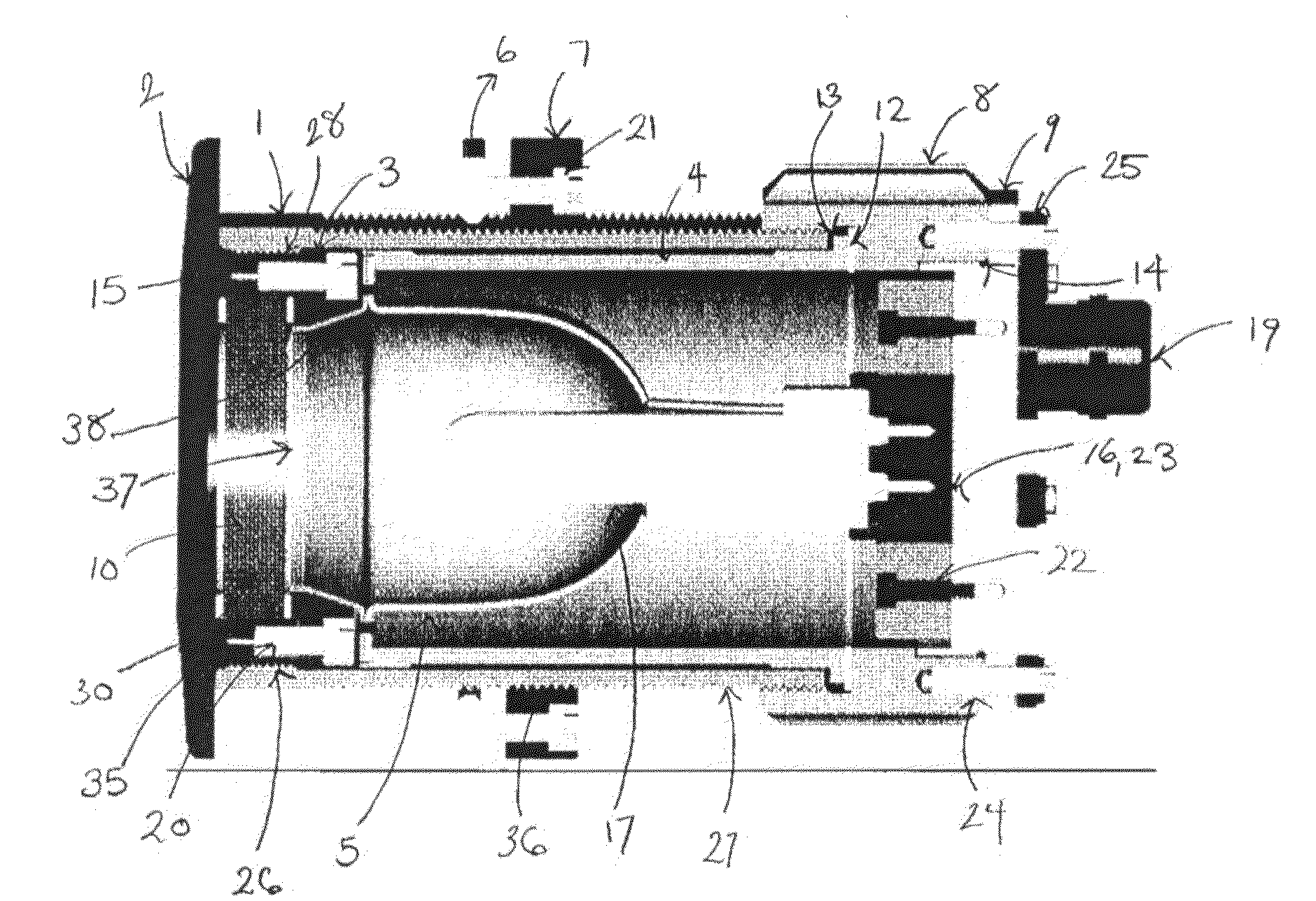
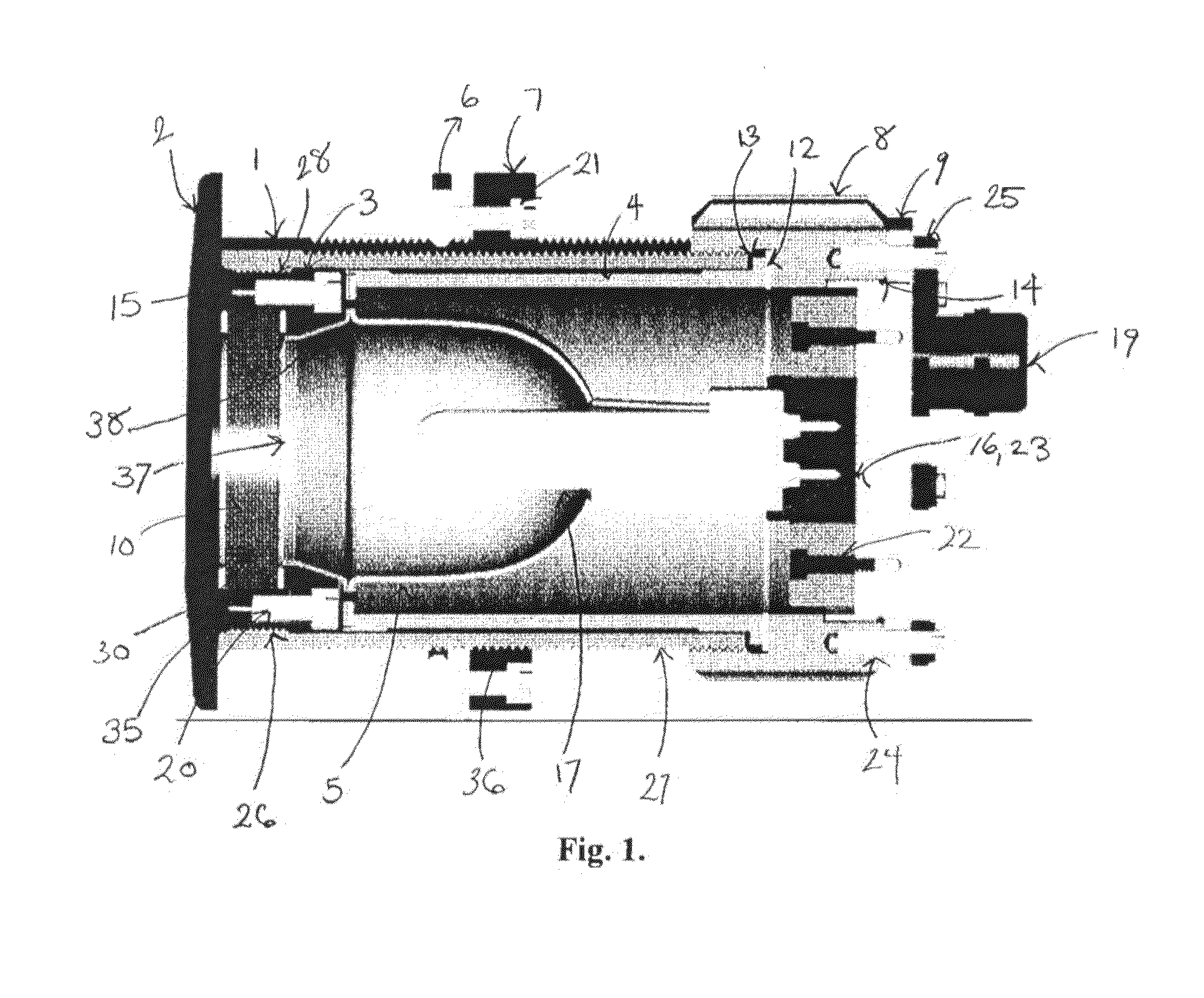
[0023]The present invention is a thru-hull view port assembly that can serve as an underwater light and is constructed to have a watertight fit in the hull or deck of a vessel. Referring to FIG. 1, a flange 2 having an inner and outer face is used to mount the assembly to the exterior of the vessel. A substantially transparent lens 10 having a top and a bottom surface is removably mounted on the inner surface of the flange 2.

[0024]Lens 10 is in the shape of a disc with ground edges and is preferably composed of heat and pressure resistant borosilicate glass. As will be appreciated by one of skill in the art, any substantially transparent material that is resistant to high temperature and high pressure and is resistant to erosion and chemicals can be used. Suitable materials include chemically hardened or tempered and impact resistant materials such as quartz glass, tempered (Pyrex), borosilicate, or sapphire crystal may also be used. The glass disc is retained in place by glass reta...


PUM


Abstract

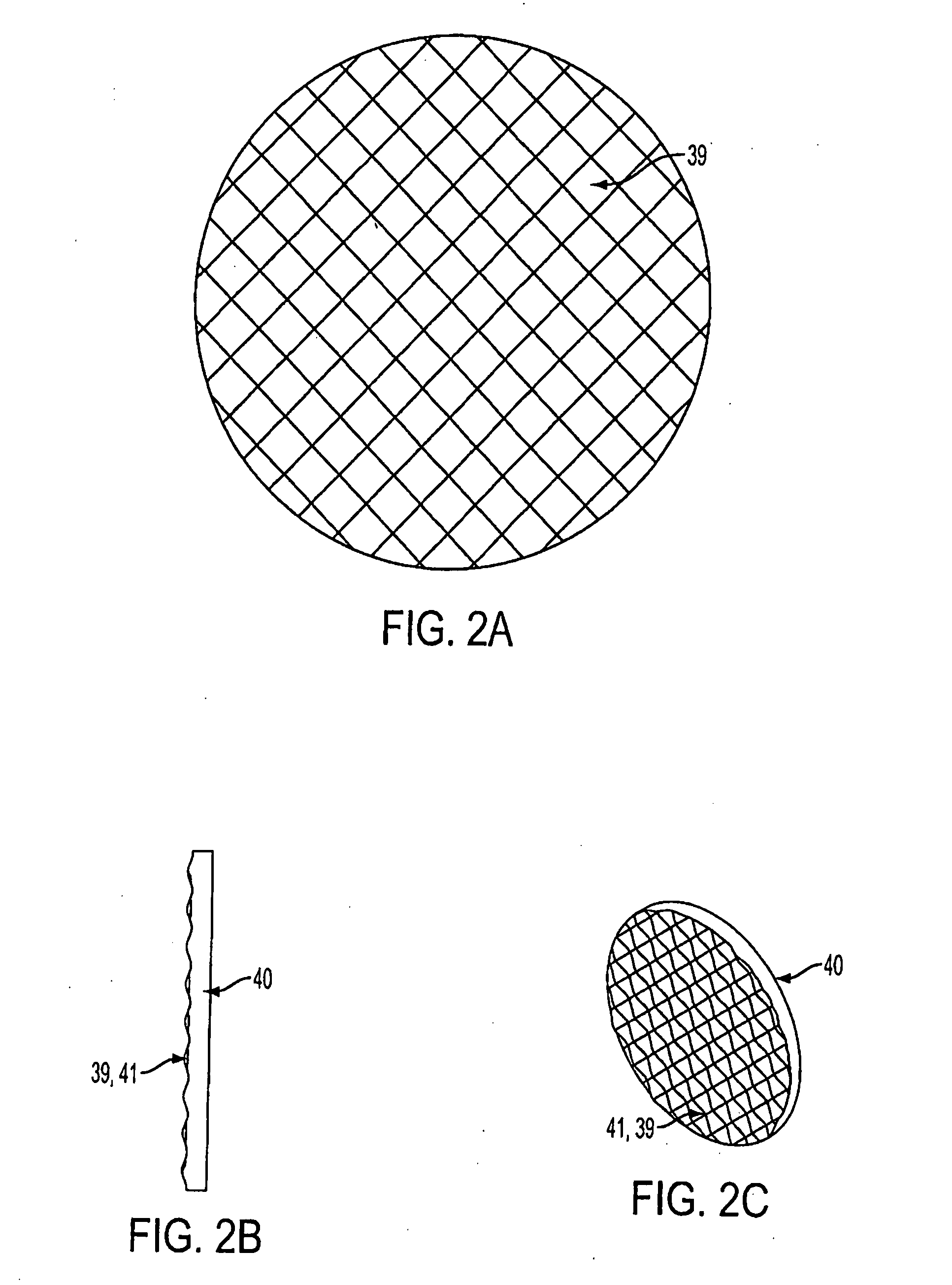
The present invention is a thru-hull light for installation under the waterline of a vessel comprising a lens capable of diffusing the light broadly through the water. In a preferred embodiment, the lens is a separate, discrete component with a prismatic surface.

Description

[0001]This application is related to, cross references and incorporates by reference the subject matter of provisional No. 60 / 781,678 filed on Mar. 13, 2006 and provisional No. 60 / 715,625 filed on Sep. 9, 2005.BACKGROUND OF INVENTION[0002]Underwater view ports have been used on ships, boats or other watercraft for decorative and safety purposes as well as to aid exploration of the surrounding water. Similarly lighting has been applied to these same watercraft to improve visibility during the dark hours or during periods of overcast or cloudy conditions. Lights have been applied so as to illuminate the sides of the watercraft in order to better visualize the watercraft from a distance, to further enhance the appearance of the watercraft, and to illuminate the surrounding water area. Lights have been mounted in various locations on the deck or hull of the watercraft to accomplish this purpose.[0003]Conventional view ports use a frame to mount a substantially transparent window to the ...

Claims


Application Information

Patent Timeline
IPC IPC(8): B60Q1/00
CPCB63C11/49B63B45/02
Inventor RASH, RANDALMACDONALD, IAN
Owner UNDERWATER LIGHTS USA
Learn More