
Data input pen with photographing function and photographing range laser positioning method thereof

A technology of data and functions, applied in the field of computer peripheral input devices, can solve the problems of no photo supplementary light, failure to meet the requirements of image information input, and inability to achieve real restoration, etc., to solve the problem of weak light intensity and increase photo supplementary light and the effect of astigmatism structure

Pending Publication Date: 2019-09-10
山东积至电子有限公司
View PDF0 Cites 4 Cited by
  • Summary
  • Abstract
  • Description
  • Claims
  • Application Information

AI Technical Summary

Problems solved by technology

The picture synthesis effect cannot be guaranteed at all, and the real restoration cannot be achieved, and the picture information entry requirements cannot be met.
[0003] The existing scanning pen does not have the function of taking pictures at a longer distance, nor can it realize the effective selection and positioning of the shooting range
[0004] Since the existing scanning pen does not have a long-distance camera function, of course there is no camera fill light function

Method used


Image

  • Data input pen with photographing function and photographing range laser positioning method thereof
  • Data input pen with photographing function and photographing range laser positioning method thereof
  • Data input pen with photographing function and photographing range laser positioning method thereof

Examples


Embodiment 1

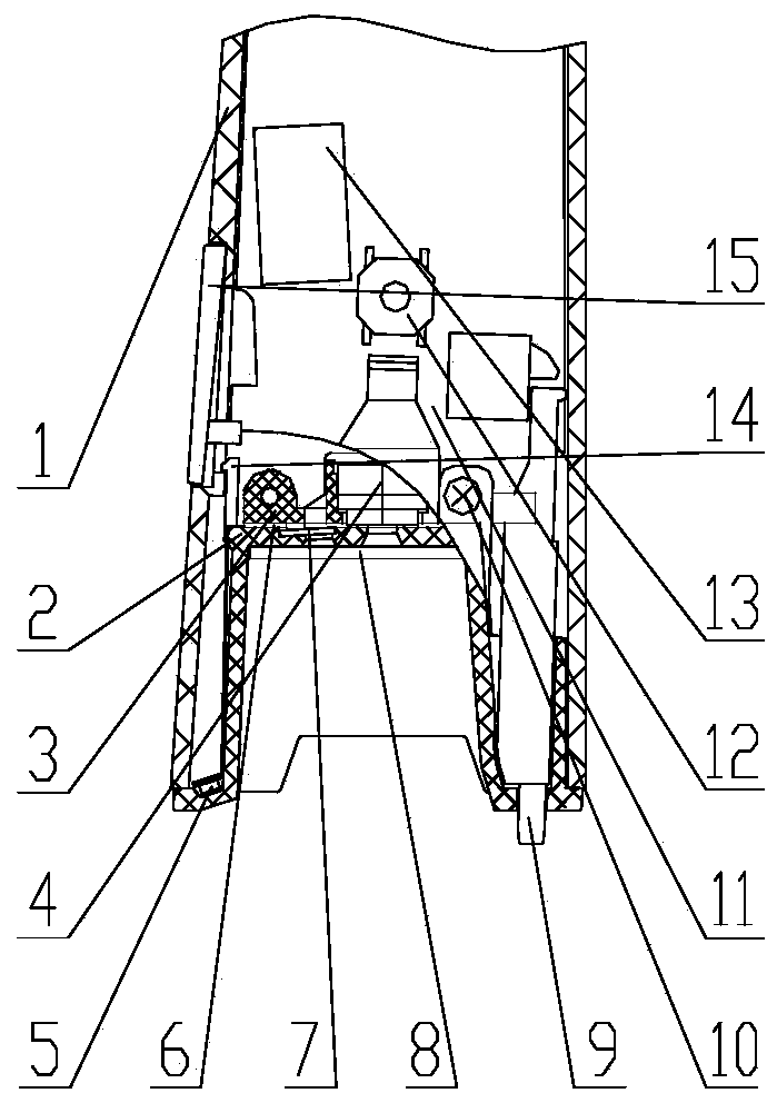
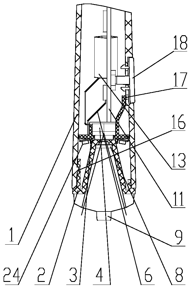
[0037] Such as Figure 1-3 As shown, the data entry pen with camera function in this embodiment includes a camera 4, a laser emitter 13 and a grating lens 7.

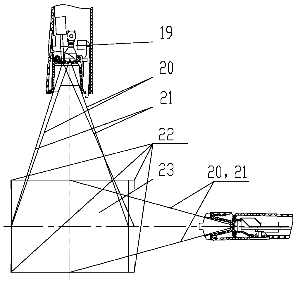
[0038] Wherein, the laser emitter 13 cooperates with the grating lens 7, when the laser emitter 13 emits the laser beam 19, the laser beam 19 generates diffraction when passing through the grating lens 7, and the laser beam disperses into a mark frame and strikes on the object to be photographed. The laser beam 19 is preferably a red laser beam. The marking frame is formed by at least one peripheral laser cursor 22 , and the marking frame refers to the cursor range enclosed by the at least one peripheral laser cursor 22 .

[0039] Both the laser emitter 13 and the camera 4 are set to face the object to be photographed, and the marking frame and the photographing range 23 of the camera 4 overlap at least partially, preferably approximately, on the plane of the object to be photographed. The so-called "approximately ove...

Embodiment 2

[0066] A method for laser positioning of a photographing range, using the above-mentioned data entry pen with a photographing function, comprising the following steps:

[0067] Step 1: The laser emitter 13 emits a laser beam 19, and the laser beam 19 passes through the grating lens 7 to form a marked frame on the object to be photographed;

[0068] Step 2: Move the marked frame and position it on the approximate photographing range 23 where you want to photograph;

[0069] Step 3: The camera 4 takes pictures of the subject to be photographed.

[0070] Advantageously, the camera 4 and the laser transmitter 13 are all connected to the camera switch 12; when the first action is applied to the camera switch, step 1 is performed, and when the second action is applied to the camera switch, step 3 is performed, and the laser transmitter 13 closure.

[0071] It also includes a photographing supplementary light 5. When step 3 is performed, the photographing supplementary light 5 is p...


PUM


Abstract

The invention discloses a data input pen with a photographing function and a photographing range laser positioning method thereof. The data input pen comprises a camera, a laser emitter and a gratinglens, wherein the laser emitter is matched with the grating lens, when the laser emitter emits a laser beam, the laser beam penetrates through the grating lens to form a marking picture frame, the laser emitter and the camera are both arranged to face a photographed object, and the photographing ranges of the marking picture frame and the camera are at least partially overlapped on the plane of the photographed object. The scanning pen solves the problem that an existing scanning pen can only perform near-scene scanning but cannot perform far-scene photographing. The data input pen is not provided with a display screen for a photographer to effectively select the photographing range, so that the photographing range is identified by using the cursor range through a method of laser markingand actual photographing range coincidence by using a technical means, and the photographer can effectively select the photographing range according to the cursor identification range so as to accurately photograph the photographing range.

Description

technical field [0001] The invention relates to the field of computer peripheral input devices, in particular to a data entry pen with a camera function. Background technique [0002] Scanning pens currently on the market can only scan and input text at close range (close to the paper surface). If you want to input larger image information, you need to scan the image multiple times in staggered lines, and then recombine it. The picture synthesis effect cannot be guaranteed at all, and the real restoration cannot be achieved, and the picture information entry requirements cannot be met. [0003] The existing scanning pen does not have the function of taking photos at a relatively long distance, and it is also impossible to effectively select and locate the range of photos taken. [0004] Since the existing scanning pen does not have the function of taking pictures at a longer distance, it certainly does not have the function of supplementing light for taking pictures. Cont...

Claims


Application Information

Patent Timeline
Patent Type & Authority Applications(China)
IPC IPC(8): H04N1/107H04N1/028H04N5/225
CPCH04N1/107H04N1/0282H04N23/56
Inventor 不公告发明人
Owner 山东积至电子有限公司
Learn More