Plate punching die

A technology for punching dies and plates, applied in the field of stamping tooling for U-shaped plates, which can solve problems such as low efficiency and insufficient use of plates, and achieve high utilization and full use

Pending Publication Date: 2019-09-13
施密特电梯有限公司
View PDF0 Cites 1 Cited by
  • Summary
  • Abstract
  • Description
  • Claims
  • Application Information

AI Technical Summary

Problems solved by technology

[0003] The purpose of the present invention is to solve the above-mentioned technical problems and provide a sheet punching die, which effectively solves the technical problems of low efficiency and insufficient use of sheet metal

Method used


Image

  • Plate punching die
  • Plate punching die
  • Plate punching die

Examples


Embodiment Construction

[0015] The implementation of the present invention will be illustrated by specific specific examples below, and those skilled in the art can easily understand other advantages and effects of the present invention from the contents disclosed in this specification.

[0016] Below in conjunction with accompanying drawing and embodiment the present invention will be further described:

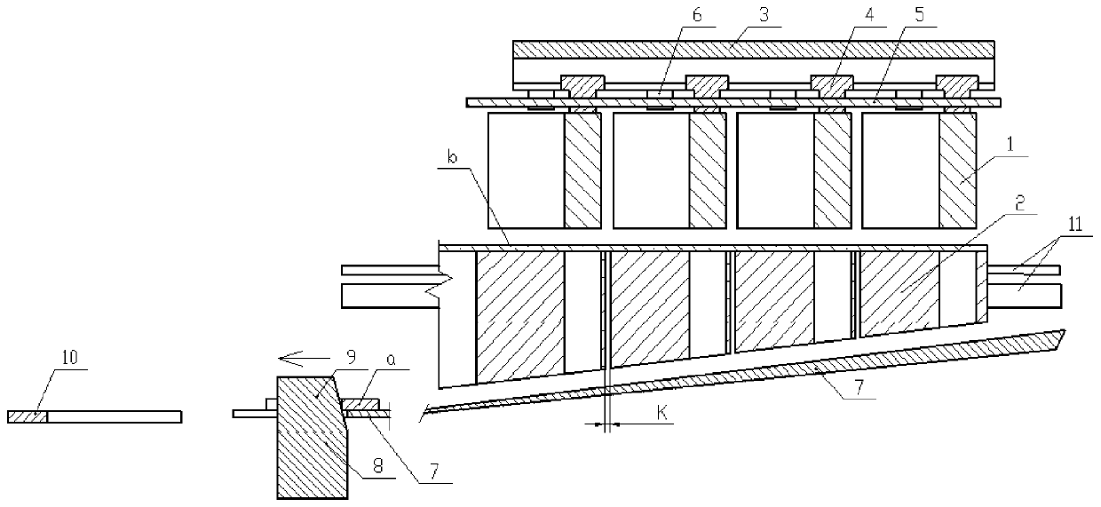
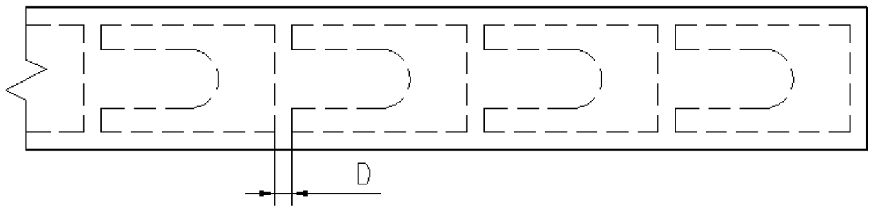
[0017] Such as figure 1 As shown, a plate punching die mainly includes an upper die 1 and a lower die 2, the horizontal section of the upper die 1 is U-shaped, and the lower die 2 has a U-shaped die hole corresponding to the upper die 1, and the upper die 1 is located directly above the lower die 2 and makes the upper die 1 just inserted into the U-shaped die hole of the lower die 2 when it moves down to punch out the U-shaped part a.

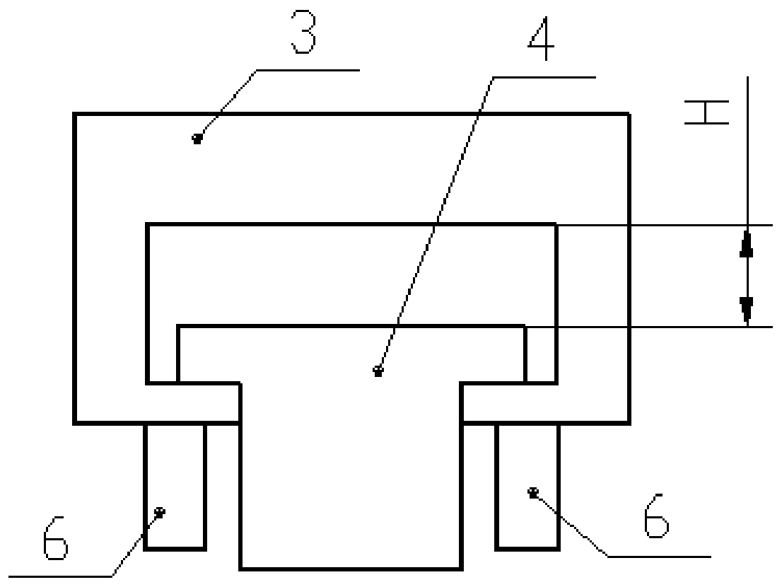
[0018] There are several upper dies 1 and lower dies 2 with the same number, a T-shaped slider 4 is fixedly connected to the top of the upper die 1, and the T-shap...


PUM


Abstract

The invention discloses a plate punching die. The horizontal cross sections of upper dies are in U shapes; lower dies are provided with U-shaped die holes corresponding to the upper dies; the upper dies are located right above the lower dies; when the upper dies move downwards, the upper dies are just inserted into the U-shaped die holes of the lower dies so as to punch out U-shaped pieces; the multiple upper dies and the multiple lower dies are arranged; the quantities of the upper dies and the lower dies are consistent; T-shaped sliding blocks of the upper dies are in sliding fit with sliding chutes arranged in a pressing beam along a linear direction of upper die arrangement; a section of stroke distance is left between the top surface of each T-shaped sliding block and a groove bottomof the corresponding sliding chute; the gap between each two adjacent lower dies can be adjusted through an adjusting mechanism; the upper ends of the lower dies are planes; the lower ends of the lower dies are inclined surfaces which are downwards inclined toward one sides of openings of the U-shaped structures of the U-shaped die holes; conveying plates are arranged under the inclined surfaces in parallel; and a strip-shaped notch formed along a U-shaped piece conveying direction is formed in the output end of the bottom part of each conveying plate. The die punching and finished product transferring efficiency is high, and materials are fully utilized.

Description

technical field [0001] The invention belongs to the technical field of punching, and in particular relates to a punching tool for a U-shaped plate. Background technique [0002] In the production process of the elevator, a U-shaped part similar to a U-shaped structure needs to be used. At present, such parts are usually punched in a single piece, and the punching efficiency is low. After punching, the collection of U-shaped parts is all centralized. It is time-consuming and labor-intensive to manually collect the blanked materials into piles, and because the thickness of the plates is different, it is best to have different punching intervals for the U-shaped parts when punching each board, otherwise the edge of the U-shaped part after punching will be collapsed. 1. The napping is not equal, and the length of the material board is different, which often causes too much material head after punching, and the board material is not fully utilized. Contents of the invention ...

Claims


Application Information

Patent Timeline
Patent Type & Authority Applications(China)
IPC IPC(8): B21D28/14B21D43/12B21D43/22
CPCB21D28/14B21D43/12B21D43/22
Inventor 毛先金
Owner 施密特电梯有限公司
Why Eureka
Try Eureka