Deep vertical displacement monitoring point device

A technology of vertical displacement and monitoring points, applied in the direction of measuring devices, mechanical measuring devices, and mechanical devices, etc., can solve the problems of affecting the observation accuracy of soil settlement, reducing construction efficiency, troublesome backfilling and compaction, and achieving difficult monitoring deviation and connection. Easy to operate and achieve the effect of synchronous settlement

Pending Publication Date: 2019-09-13
HUNAN LIANZHI BRIDGE & TUNNEL TECH +1
View PDF8 Cites 0 Cited by
  • Summary
  • Abstract
  • Description
  • Claims
  • Application Information

AI Technical Summary

Problems solved by technology

[0004] In the above scheme, although the length of the monitoring point can be adjusted at will, and the bottom of the measuring head and the monitoring point is specially treated to improve the measurement accuracy and effect, but the measuring head, the measuring rod, the connecting piece of the measuring rod, and the connection between the measuring rod and the sleeve The parts are all fixed by screwing, and the stability is poor. Generally, there is groundwater in the deep layer of the soil, and the soil is relatively humid, and the water is easy to erode the connecting parts. Due to its poor stability, under the extrusion of the soil, This leads to the loosening of the measuring rod, which seriously affects the settlement observation accuracy of the soil. In addition, although the setting of the sleeve can increase the connection force with the soil, due to its own cylindrical characteristics, the increase in the connection force is limited, and it is easy to The phenomenon of detachment from the soil occurs, and in order to embed the sleeve during construction, the diameter of the borehole is slightly larger, and backfilling and compaction is also more troublesome, reducing construction efficiency

Method used


Image

  • Deep vertical displacement monitoring point device
  • Deep vertical displacement monitoring point device
  • Deep vertical displacement monitoring point device

Examples


Embodiment 1

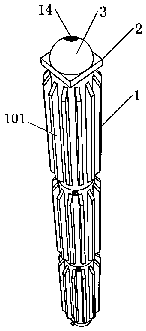
[0035] see Figure 1-5 , a deep vertical displacement monitoring point device, including a probe device and a measuring rod 1, the measuring rod 1 includes at least one sub-rod 101, and the axial ends of the sub-rod 101 are respectively provided with a docking port and a docking platform 5. The probe device is provided with a docking port or a docking platform 5, and the connection between the probe device and the adjacent sub-rods is realized through the cooperation of the docking port and the docking platform 5. Multiple sub-rods 101 are coaxially arranged and passed through the corresponding The cooperation between the docking ports between the adjacent sub-poles and the docking platform 5 realizes the end-to-end sequential connection;

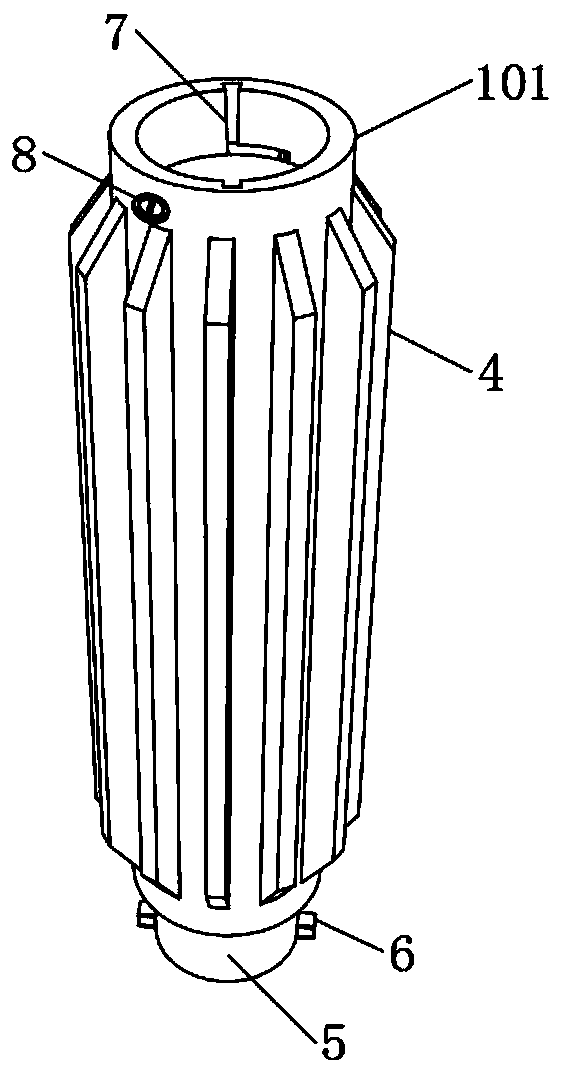
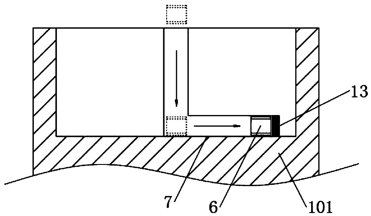
[0036] see figure 2 with image 3 , the inner wall of the docking port is provided with at least one lock slot 7, the outer wall of the docking table 5 is provided with a displacement lock block 6 matching the lock slot, the docking tabl...


PUM


Abstract

The invention provides a deep vertical displacement monitoring point device. The deep vertical displacement monitoring point device comprises a measuring head device and a measuring rod; the measuringrod comprises at least one sub-rod; two axial ends of the sub-rod are respectively provided with an abutting joint hole and an abutting joint platform; the measuring head device is provided with theabutting joint hole or the abutting joint platform; due to matching of the abutting joint hole and the abutting joint platform, connection between the measuring head device and the adjacent sub-rod isrealized; multiple sub-rods are coaxially arranged, and sequentially connected end to end through matching of the abutting joint hole and the abutting joint platform between the adjacent sub-rods; atleast one locking slot is arranged on the inner wall of the abutting joint hole; a displacement locking block matched with the locking slot is arranged on the outer wall of the abutting joint platform; the abutting joint platform is inserted into the abutting joint hole; and furthermore, connection of the two is realized through matching of the displacement locking block and the locking slot. Thedevice in the invention can effectively prevent the monitoring result deviation condition due to a gap between the sub-rods; and in addition, due to arrangement of a sealing part, soil and water in asoil body can be effectively prevented from corroding the interior of the device.

Description

technical field [0001] The invention relates to the technical field of engineering monitoring, in particular to a deep vertical displacement monitoring point device. Background technique [0002] At present, most of the deep vertical displacement monitoring points commonly used in engineering use a whole steel bar or self-made iron rod. When different depth monitoring points need to be laid out, they need to be processed separately, and the versatility is poor; Do any special treatment, when the surface of the top ruler is not flat, the monitoring accuracy will be greatly affected due to the different positions of the ruler and the ruler each time; while the bottom is not treated, it only depends on the friction between the monitoring point itself and the surrounding soil When the force is used to respond to the subsidence of the ground, it is easy for the monitoring point to be separated from the surrounding soil, and the monitoring point cannot truly reflect the deformatio...

Claims


Application Information

Patent Timeline
IPC IPC(8): G01C5/00G01B5/02
CPCG01C5/00G01B5/02
Inventor 梁晓东邱志勇任沙杨振武刘正兴谢鸿金鑫
Owner HUNAN LIANZHI BRIDGE & TUNNEL TECH
Why Eureka
Try Eureka