
Extrusion runner improved structure of plastic extruder

A plastic extruder and extruder technology, which is applied in the field of improving the structure of the extrusion channel of the plastic extruder, can solve the problems of inconvenient connection, large resistance, and inconvenient material flow, etc., so as to achieve fast and convenient connection operation, increase The effect of increasing the amount of material extruded and improving production efficiency

Inactive Publication Date: 2018-03-09
TIANJIN TIANSU SCI & TECH GROUP
View PDF0 Cites 0 Cited by
  • Summary
  • Abstract
  • Description
  • Claims
  • Application Information

AI Technical Summary

Problems solved by technology

[0002] In the existing film production technology, extrusion operation is an indispensable production link, and the extruder determines the maximum production capacity of the equipment. However, the extrusion channel connected to the traditional extruder and the head is a 90° right-angle structure , the actual flow channel structure formed is unreasonable, resulting in large resistance, which is not convenient for material flow, and often there will be insufficient material supply, stagnation in dead ends or retention, especially for the production of wide-width films, when the film width reaches a certain limit , the extrusion volume cannot meet the demand of wide-width film production, which affects the production efficiency
In addition, the right-angle structure of the extrusion flow channel is extremely inconvenient to connect when installing the equipment

Method used


Image

  • Extrusion runner improved structure of plastic extruder

Examples


Embodiment Construction

[0011] In order to further understand the invention content, characteristics and effects of the present invention, the following examples are given, and detailed descriptions are as follows in conjunction with the accompanying drawings:

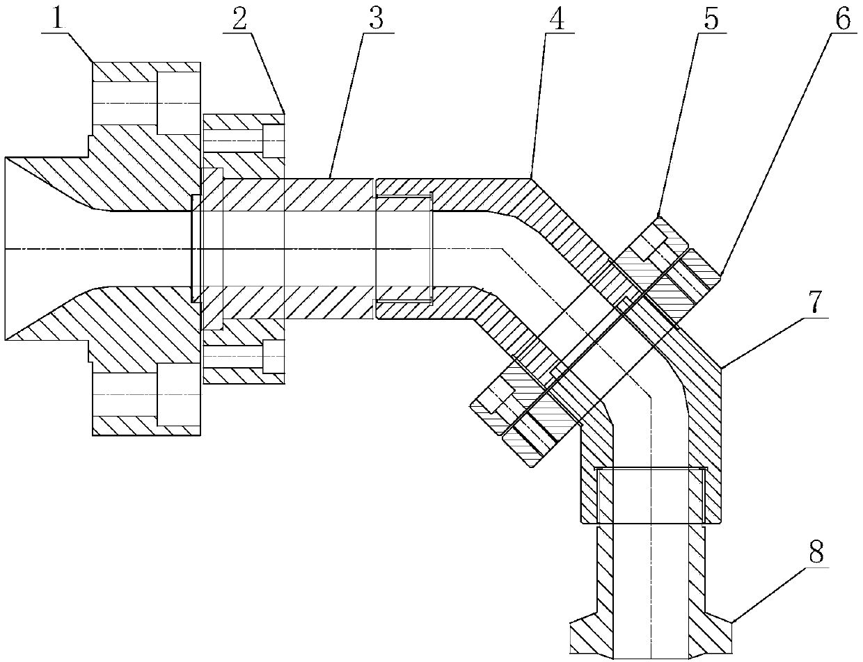
[0012] see figure 1 , the improved structure of the extrusion flow channel of the plastic extruder, including the first connecting part 1 connected to the discharge port of the extruder, the flow channel body 3, the first elbow 4, the second elbow 7 and the connection with the machine head The second connection part 8 . The first connecting part is connected to the flow channel body 3 through the clamping block 2 and bolts, so as to prevent material leakage at the connecting part of the two. The other end of the runner body 3 is threaded to the first elbow 3, the first elbow is threaded to the first flange 5, the second elbow is threaded to the second flange 6, and the first method The flange and the second flange are fixed by fastening scr...


PUM


Abstract

The invention relates to an extrusion runner improved structure of a plastic extruder. The extrusion runner improved structure comprises a first connection part, a runner body, a first elbow, a secondelbow and a second connection part, and is characterized in that the first connection part is connected with the runner body by virtue of a clamping block and a bolt, the other end of the runner bodyis connected with the first elbow in a threading manner, the first elbow is connected with a first flange in a threading manner, the second elbow is connected with a second flange in a threading manner, the first flange and the second flange are fixedly connected by virtue of a tightening screw, the other end of the second elbow is connected with the second connection part in a threading manner,a bending angle of the first elbow and second elbow is separately greater than 90 degrees, and a continuous smooth transitional material runner is formed in an inner cavity of the first elbow and second elbow. The extrusion runner improved structure of the plastic extruder has the advantages that the inner cavity of the extrusion runner can form the continuous smooth transitional material runner,the phenomenon such as dead corner stagnation, insufficient material supply or residue of the material can be avoided; and the material extrusion amount is increased, and the resistance applied to thematerial in the extrusion process can be reduced. The extrusion amount and processing demand for the wide-amplitude film production can be satisfied, and the production efficiency can be improved.

Description

technical field [0001] The invention belongs to the technical field of plastic processing machinery, and in particular relates to an improved structure of an extrusion channel of a plastic extruder. Background technique [0002] In the existing film production technology, extrusion operation is an indispensable production link, and the extruder determines the maximum production capacity of the equipment. However, the extrusion channel connected to the traditional extruder and the head is a 90° right-angle structure , the actual flow channel structure formed is unreasonable, resulting in large resistance, which is not convenient for material flow, and often there will be insufficient material supply, stagnation in dead ends or retention, especially for the production of wide-width films, when the film width reaches a certain limit , the extrusion volume cannot meet the production demand of wide-width film, which in turn affects the production efficiency. In addition, the ext...

Claims


Application Information

Patent Timeline
Patent Type & Authority Applications(China)
IPC IPC(8): B29C47/12B29L7/00B29C48/30
CPCB29C48/30B29L2007/00
Inventor 郝福江王全有赵海浩杨渝裴杨
Owner TIANJIN TIANSU SCI & TECH GROUP
Learn More