
A shield cutter

A shield cutter and cutter head technology, applied in mining equipment, tunnels, earth-moving drilling, etc., can solve the problems of increased scraper wear, shortened scraper life, multiple damages, etc., to improve protection, prolong service life, and prevent damage. Effect

Active Publication Date: 2020-06-19
ERCHU CO LTD OF CHINA RAILWAY TUNNEL GRP
View PDF5 Cites 0 Cited by
  • Summary
  • Abstract
  • Description
  • Claims
  • Application Information

AI Technical Summary

Problems solved by technology

[0004] The scraper is fixedly installed on the cutter head. During the excavation process, the scraper is in direct contact with soil, rocks and other objects. Since the scraper has no space for a buffer mechanism, the scraper is still "head-to-head" when encountering an object harder than the scraper. Construction in a hard environment, the probability of this situation is relatively high, which will increase the wear of the scraper, shorten the life of the scraper, and increase the frequency of replacement
In severe cases, the scraper will break, and the broken cutter body is likely to directly collide with other cutters with the rotation of the cutterhead, causing other cutters to be worn to varying degrees, resulting in multiple damages

Method used


Image

  • A shield cutter
  • A shield cutter
  • A shield cutter

Examples


Embodiment Construction

[0034] Embodiments of the technical solutions of the present invention will be described in detail below in conjunction with the accompanying drawings. The following examples are only used to illustrate the technical solutions of the present invention more clearly, and therefore are only examples, rather than limiting the protection scope of the present invention.

[0035] It should be noted that, unless otherwise specified, the technical terms or scientific terms used in this application shall have the usual meanings understood by those skilled in the art to which the present invention belongs.

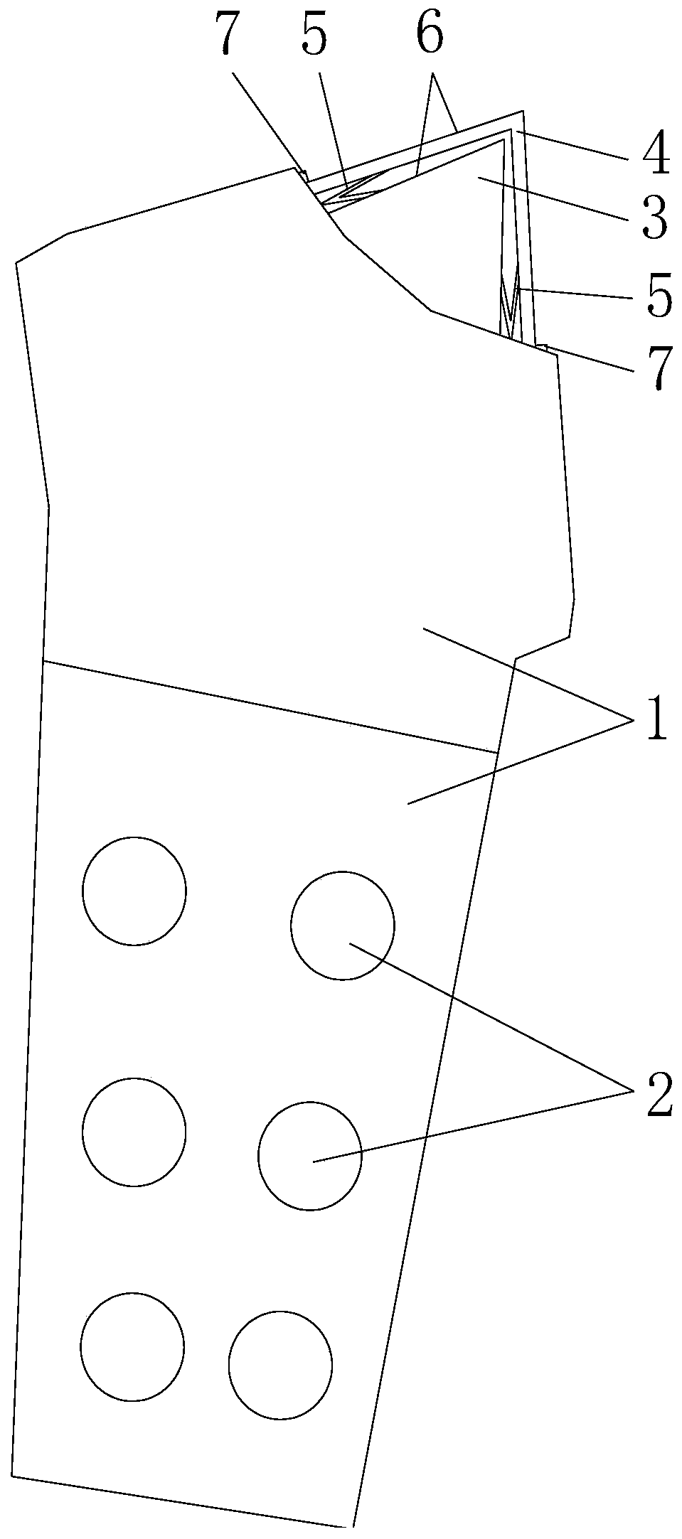
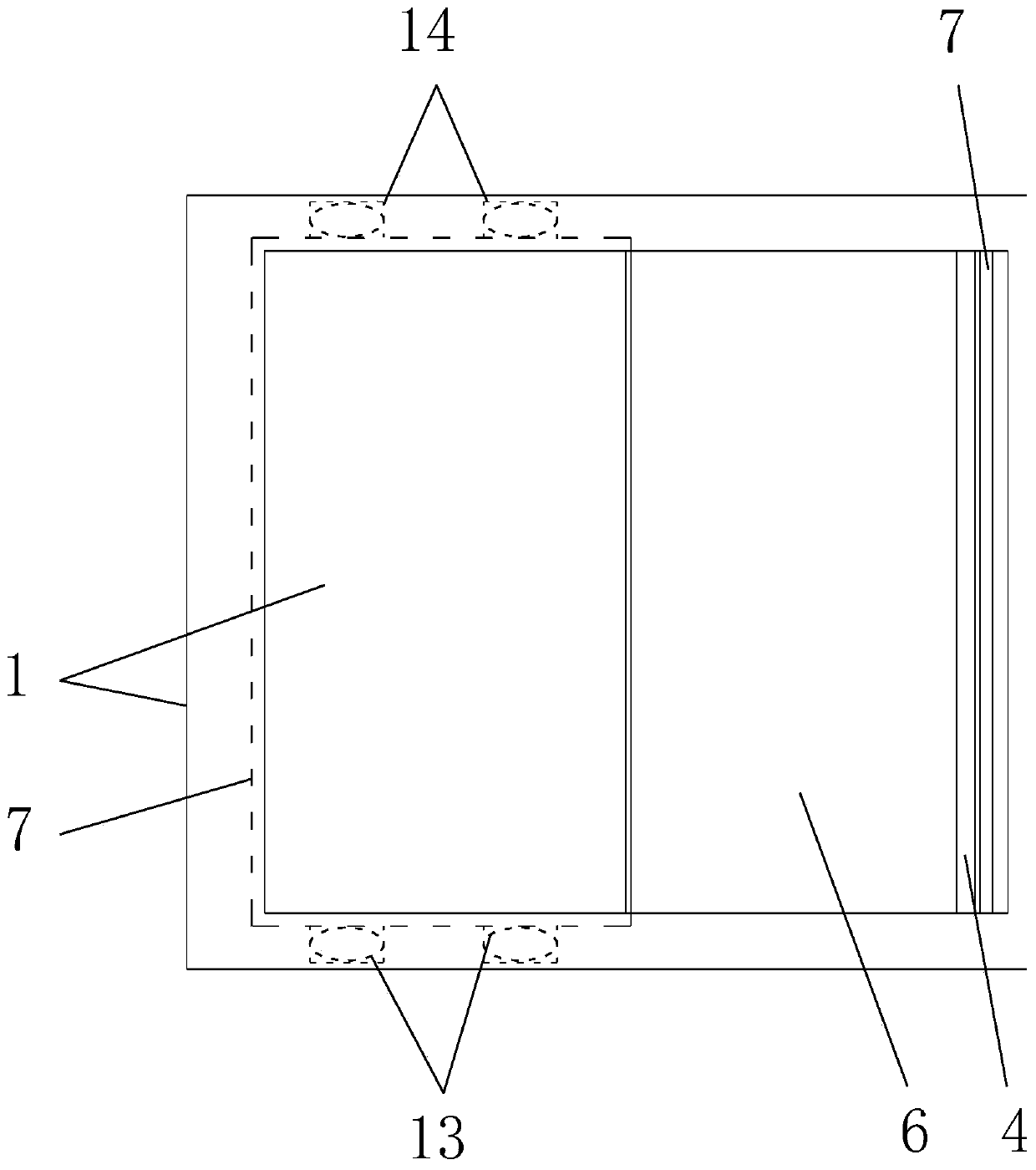
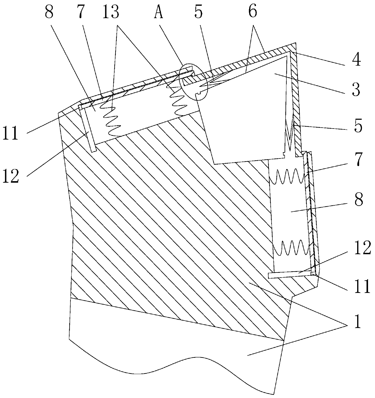
[0036] Such as figure 1 As shown, this embodiment provides a shield cutter, including a main cutter head 3 and a cutter body 1 , the main cutter head 3 is installed on the cutter body 1 , and the main cutter is fixedly connected to the cutter body 1 . Wherein the cutter body 1 is provided with six installation holes 2 for installation. In order to prolong the service life of the wh...


PUM


Abstract

The invention discloses a shield cutter. The shield cutter comprises a main cutter head and a cutter body, and the main cutter head is mounted on the cutter body; the shield cutter further comprises avice cutter head and a buffer; the cross section of the vice cutter head is in an L shape, the vice cutter head covers two cutting surfaces of the main cutter head, and a buffer space is formed between the main cutter head and the vice cutter head; and the buffer is mounted between the main cutter head and the vice cutter head and is used for resetting the vice cutter head. According to the shield cutter, the service life of a scraping knife is prolonged, and secondary or multiple damages of other cutters are avoided.

Description

technical field [0001] The invention relates to the technical field of shield machine equipment, in particular to a shield cutter. Background technique [0002] A shield machine is a tunnel boring machine that uses the shield method. The construction method of shield tunneling is the "shield" (referring to the supporting segment) of the tunnel constructed (laid) by the roadheader while excavating, which is different from the open construction method. [0003] The shield machine is mainly composed of 9 parts, which are the shield body, cutterhead, double-chamber airlock, segment assembly machine, soil discharge mechanism, rear supporting device, electrical system and auxiliary equipment. The cutter head is a cutting disc body with multiple feeding grooves, which is located at the front of the shield machine and is used for cutting soil. A variety of knives are installed on the cutter head, including center knives, hobs, scrapers, over-digging knives, etc. Since these knives...

Claims


Application Information

Patent Timeline
Patent Type & Authority Patents(China)
IPC IPC(8): E21D9/08
Inventor 刘道炎陈先智杨秀兵胡洋黎忠杨小龙张辉钱义隆时荣左银波代明建宋伟杨洋王彪李志军张成勇岳振敏宝青峰蒋树锋董书滨
Owner ERCHU CO LTD OF CHINA RAILWAY TUNNEL GRP
Learn More