Buried pipeline non-contact stress real-time monitoring method

A buried pipeline and non-contact technology, which is applied in the direction of measuring, measuring devices, and measuring magnetic variables by measuring the change of magnetic properties of materials caused by applied stress. It can solve pipeline failure and fracture, limited installation and use, etc. problems, to achieve the effect of saving excavation installation costs and low maintenance costs

Active Publication Date: 2019-09-13
SOUTHWEST PETROLEUM UNIV
View PDF8 Cites 11 Cited by
  • Summary
  • Abstract
  • Description
  • Claims
  • Application Information

AI Technical Summary

Problems solved by technology

[0006] The present invention mainly overcomes the deficiencies in the prior art, and proposes a non-contact stress real-time monitoring method for buried pipelines. The problem of limited on-site installation and use; thus avoiding failure and fracture accidents of pipelines under excessive load and stress

Method used


Image

  • Buried pipeline non-contact stress real-time monitoring method
  • Buried pipeline non-contact stress real-time monitoring method
  • Buried pipeline non-contact stress real-time monitoring method

Examples


Embodiment Construction

[0032] The present invention will be further described below in conjunction with the embodiments and the accompanying drawings.

[0033] A non-contact stress real-time monitoring method for buried pipelines of the present invention comprises the following steps:

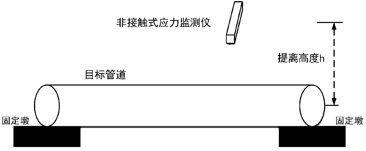
[0034] Step S10, (such as figure 2 (shown) Select a pipeline with the same material, pipe diameter and wall thickness as the buried pipeline to test the lift-off effect, and obtain multiple sets of lift-off magnetic field gradient moduli G under multiple sets of lift-off heights h 1 ;

[0035] Step S20, using matlab to fit G 1 -h relationship curve to obtain the lift-off gradient modulus G 1 The parameter a in the quantitative relationship between lift-off height h 1 , b 1 、a 2 , b 2 The numerical size of; Described quantitative relational expression is:

[0036]

[0037] In the formula: G 1 is the lift-off magnetic field gradient modulus; h is the lift-off height; a 1 , b 1 、a 2 , b 2 parameters res...


PUM


Abstract

The invention discloses a buried pipeline non-contact stress real-time monitoring method. The method comprises the following steps: selecting a pipeline with same material, pipe diameter and wall thickness with the buried pipeline to perform lift-off effect testing, and acquiring the lift-off magnetic field gradient modulus under multiple groups of lift-off heights; fitting a G1-h relation curve by utilizing matlab, and obtaining numerical values of parameters a1, b1, a2, and b2 in a quantitative relation of the lift-off gradient modulus and lift-off height; placing the non-contact type detection device above the buried pipeline to obtain the magnetic field gradient modulus of the buried pipeline; and finally computing the real-time stress of the buried pipeline according to the obtained magnetic field gradient modulus of the buried pipeline. The problems that the stress-strain gage monitoring can only reflect a stress change value and the contact-type monitoring way is limited in useat the field installation are overcome, thereby preventing the pipeline from efficiency lose and breakage accident under the excessive load and stress effect.

Description

technical field [0001] The invention relates to a non-contact stress real-time monitoring method for buried pipelines, which belongs to the field of buried pipeline stress monitoring. Background technique [0002] At present, the widely used monitoring method for buried pipelines is stress-strain gauge monitoring. Such as figure 1 As shown, commonly used strain gauges are composed of laminated films, metal resistors and plastic films. Stick the strain gauge on the pipeline to be tested, and measure the change of the stress value of the pipeline by measuring the resistance value change of the metal resistance sheet, so as to realize the monitoring of the pipeline stress. [0003] Existing monitoring has following shortcoming now: [0004] (1) According to the principle of strain gauges, stress-strain gauge monitoring cannot determine the initial stress value σ of the tested pipeline 0 , it mainly responds to the stress change value caused by pressure and load, so it canno...

Claims


Application Information

Patent Timeline
Patent Type & Authority Applications(China)
IPC IPC(8): G01L1/12
CPCG01L1/12G01B7/18G01B7/24G01M5/0025G01M5/0091G01R33/0206G01R33/091G01R33/096G01R33/09
Inventor 廖柯熹何腾蛟何国玺赵建华杨淑婷
Owner SOUTHWEST PETROLEUM UNIV
Why Eureka
Try Eureka