
Dust collector having device self-cleaning and filtering function

A self-cleaning filter and vacuum cleaner technology, which is applied in the direction of cleaning filter devices, vacuum cleaners, cleaning equipment, etc., can solve problems such as headaches for users, dirty cleaning process, dust accumulation in dust filter devices, etc.

Inactive Publication Date: 2019-09-17
艾斯美(苏州)智能科技有限公司
View PDF5 Cites 5 Cited by
  • Summary
  • Abstract
  • Description
  • Claims
  • Application Information

AI Technical Summary

Problems solved by technology

[0002] The existing vacuum cleaner includes a dust bucket assembly; an air intake pipe is provided on one side of the dust bucket assembly; a dust filter device is provided inside the dust bucket assembly; a vacuum source is provided on the upper part of the dust bucket assembly; A fan is arranged in the vacuum source; a hand-held part is arranged on one side of the dust bucket assembly; the hand-held part is arranged opposite to the air intake pipe; a battery pack is arranged on the hand-held part; the battery pack provides electric energy for the fan; When working, the fan is turned on, and the airflow enters the dust bucket assembly from the air intake pipe, and after passing through the dust filter device, the dust is filtered and collected in the dust bucket assembly, and the airflow passes through the fan and then is discharged from the battery pack; the vacuum cleaner with this structure After a long time of use, it is easy to accumulate dust on the dust filter device, and the dust bucket assembly must be disassembled to clean the dust filter device; the cleaning process is dirty and causes headaches for users

Method used


Image

  • Dust collector having device self-cleaning and filtering function
  • Dust collector having device self-cleaning and filtering function
  • Dust collector having device self-cleaning and filtering function

Examples


Embodiment Construction

[0025] The present invention will be further described in detail below in conjunction with the accompanying drawings and specific embodiments.

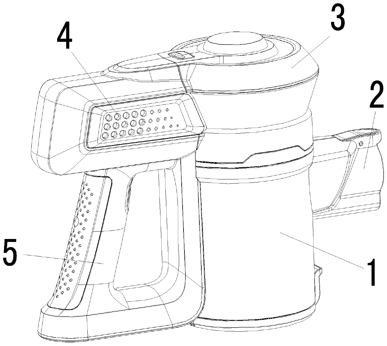
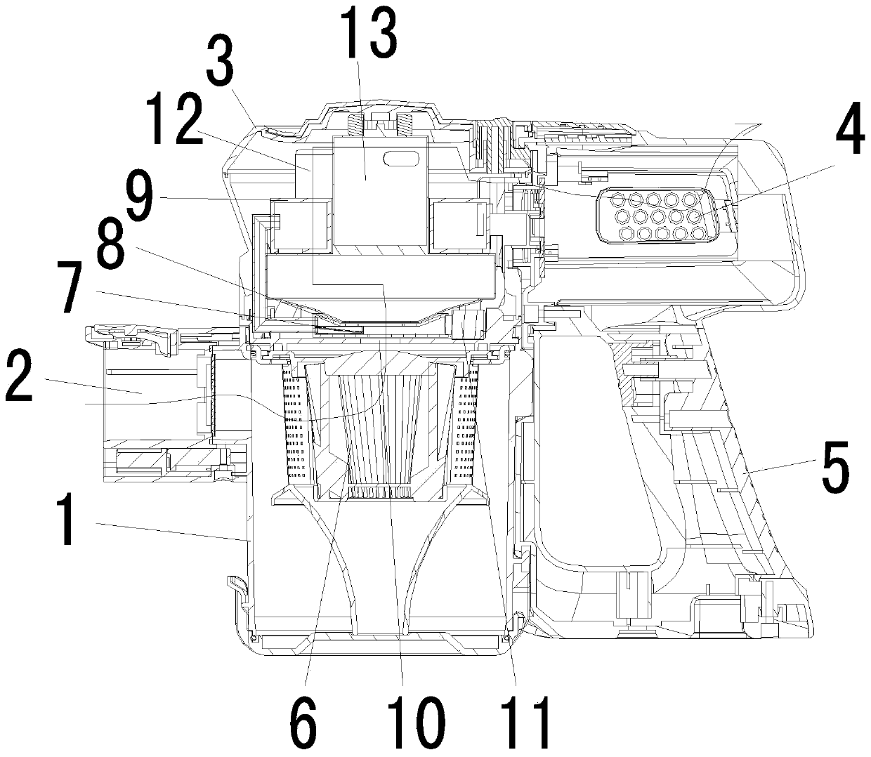
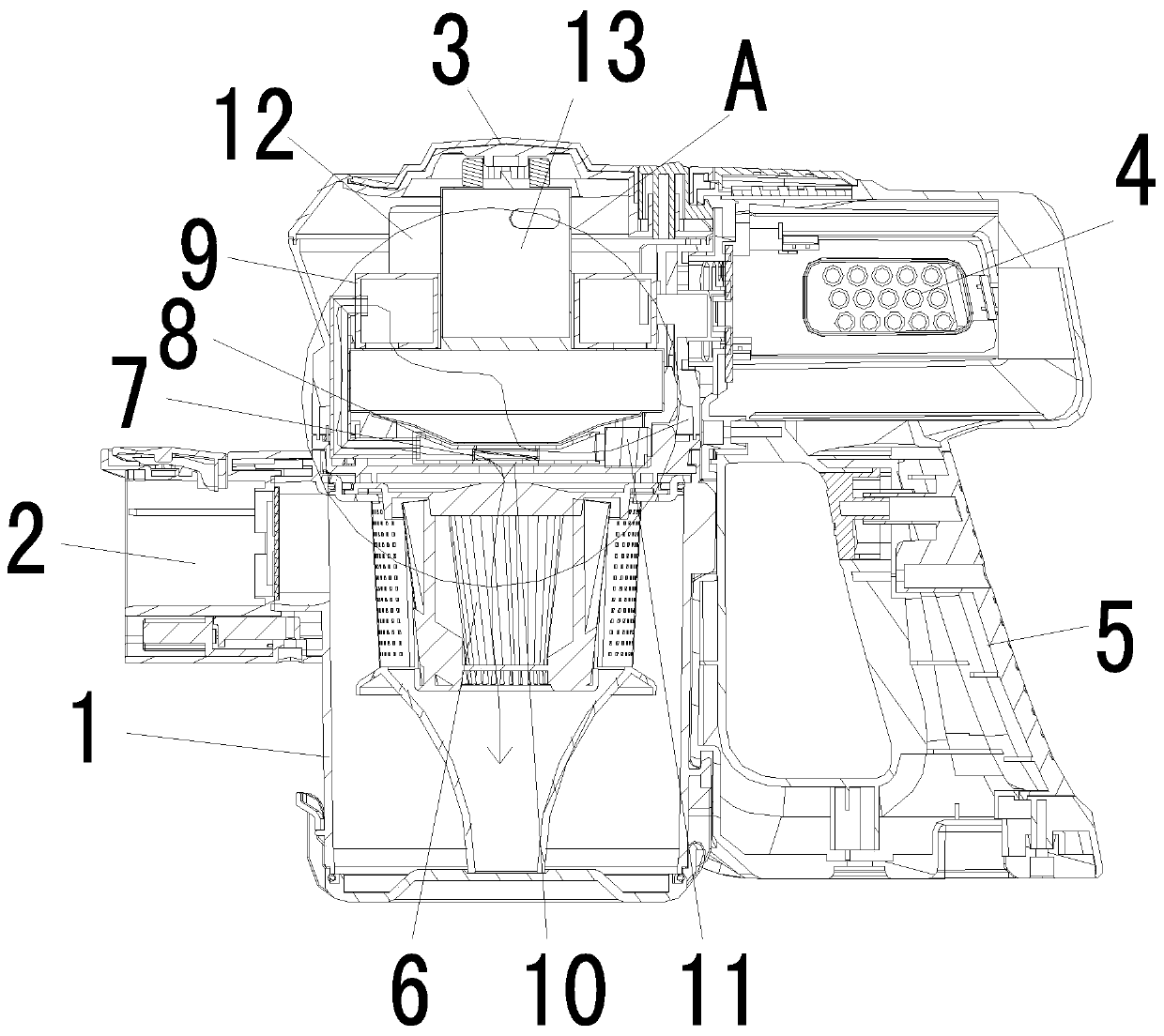
[0026] attached Figure 1-6 It is the first embodiment of the vacuum cleaner capable of self-cleaning filter device according to the present invention, which includes a dust bucket assembly 1; an air inlet pipe 2 is arranged on one side of the dust bucket assembly; the inside of the dust bucket assembly 1 is provided with Dust filtering device 6; the upper part of the dust bucket assembly 1 is provided with a vacuum source 3; the vacuum source 3 is provided with a fan 13; one side of the dust bucket assembly 1 is provided with a handle 5; the handle 5 is arranged opposite to the intake pipe 2; the hand-held part 5 is provided with a battery pack 4; the battery pack 4 provides electric energy for the fan 13; the dust bucket assembly 1 communicates with the vacuum source 3 through the first air duct 8; The first air duct 8 is provided ...


PUM


Abstract

The invention discloses a dust collector having the device self-cleaning and filtering function. The dust collector comprises a dust barrel assembly. The dust barrel assembly is communicated with a vacuum source through a first air duct. A first drainage device is arranged in the first air duct. A second air outlet is formed in the lower surface of the first drainage device. A second air duct and a third air duct which are independent of each other are arranged in the first drainage device. The second air duct is communicated with the second air outlet. Second drainage device air inlets are uniformly distributed in the lower surface of the second drainage device. A first air outlet is further formed in the upper surface of the second drainage device. The side wall of the second drainage device is communicated with the first air duct through a fourth air duct. A second air inlet is formed in the side wall of the first air duct. The first drainage device can move in the first air duct. The dust collector can be switched between the dust removal state and the self-cleaning state. The dust collector has the self-cleaning state and can be freely switched between the dust removal state and the self-cleaning state.

Description

technical field [0001] The invention relates to an improvement of a vacuum cleaner, in particular to a vacuum cleaner with a self-cleaning filter device which also has a self-cleaning state and can freely switch between a dust-removing state and a self-cleaning state. Background technique [0002] The existing vacuum cleaner includes a dust bucket assembly; an air intake pipe is provided on one side of the dust bucket assembly; a dust filter device is provided inside the dust bucket assembly; a vacuum source is provided on the upper part of the dust bucket assembly; A fan is arranged in the vacuum source; a hand-held part is arranged on one side of the dust bucket assembly; the hand-held part is arranged opposite to the air intake pipe; a battery pack is arranged on the hand-held part; the battery pack provides electric energy for the fan; When working, the fan is turned on, and the airflow enters the dust bucket assembly from the air intake pipe, and after passing through t...

Claims


Application Information

Patent Timeline
IPC IPC(8): A47L5/24A47L9/20A47L9/00A47L9/28
CPCA47L5/24A47L9/00A47L9/20A47L9/2836
Inventor 高月恒
Owner 艾斯美(苏州)智能科技有限公司
Learn More