
Brake control method for unmanned vehicle

An unmanned vehicle, braking control technology, applied in the direction of control devices, vehicle components, external condition input parameters, etc., can solve problems such as vehicle parking by mistake, bad experience, and failure to detect obstacles in time, and achieve effective braking Effects of controlling and improving driving safety

Inactive Publication Date: 2019-09-20
BEIJING ZHIXINGZHE TECH CO LTD
View PDF6 Cites 17 Cited by
  • Summary
  • Abstract
  • Description
  • Claims
  • Application Information

AI Technical Summary

Problems solved by technology

[0004] Although this kind of emergency braking scheme that only considers obstacles directly in front or behind is simple in principle and easy to implement, it has two disadvantages when the vehicle is turning: one is that if there is an obstacle directly in front of the vehicle during the turning process, the lateral When the balance wheel can pass normally, the vehicle will "stop by mistake"; secondly, when the vehicle is turning or turning around, because only the obstacles directly in front are considered, if there are obstacles on the side, it is not in the danger zone directly ahead, the vehicle will not brake urgently , leading to "false collisions"
like figure 2 As shown, the rectangle in the figure represents the unmanned vehicle, the two arcs are the future driving path of the vehicle, and the dots and triangles are obstacles. When judging emergency braking, the vehicle only judges the obstacle directly ahead, so it will trigger emergency braking at this time and stop causing bad experience; in the second case, when the vehicle is turning around, there is a dot obstacle in front of the path, but the vehicle is in the During the driving process, only the obstacles directly ahead are judged in real time, so the obstacles may not be detected in time and lead to "false collision"

Method used


Image

  • Brake control method for unmanned vehicle
  • Brake control method for unmanned vehicle
  • Brake control method for unmanned vehicle

Examples


Embodiment Construction

[0035] The technical solutions of the present invention will be described in further detail below with reference to the accompanying drawings and embodiments.

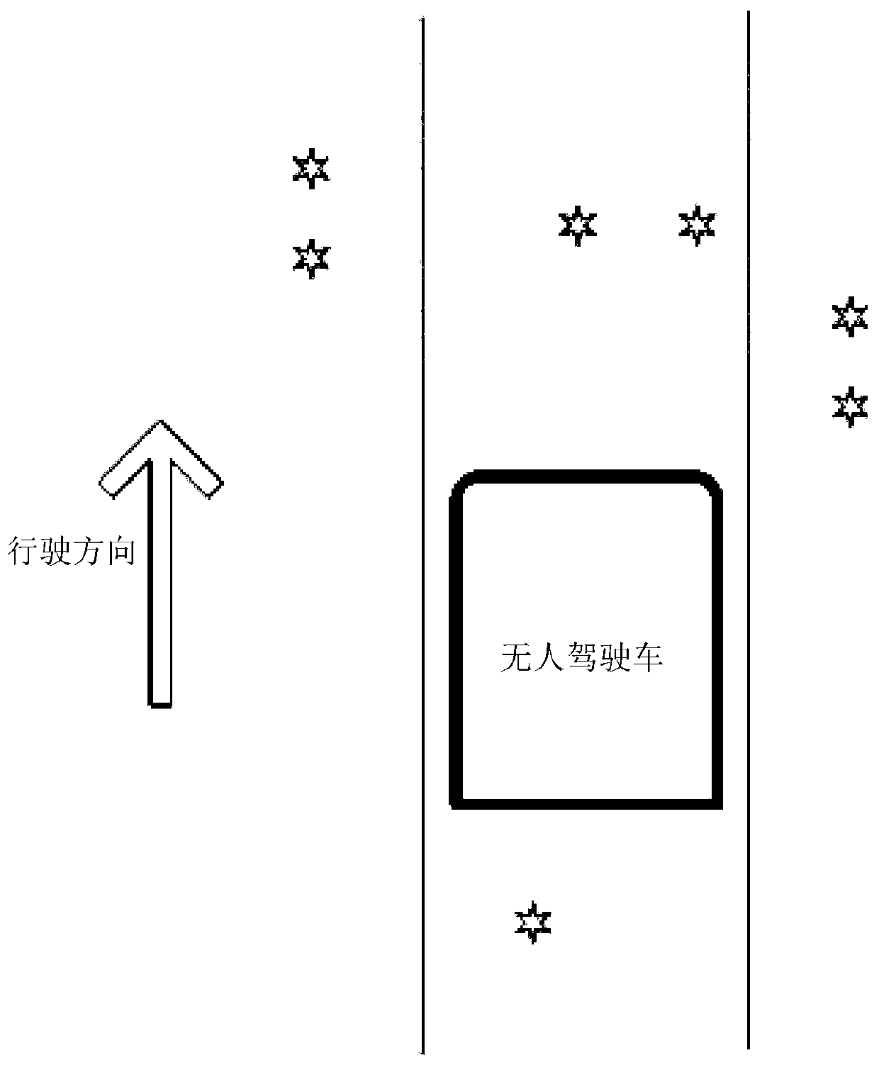
[0036] An embodiment of the present invention provides a braking control method for an unmanned vehicle, which is especially suitable for braking control when the automatic driving vehicle is turning or making a U-turn.

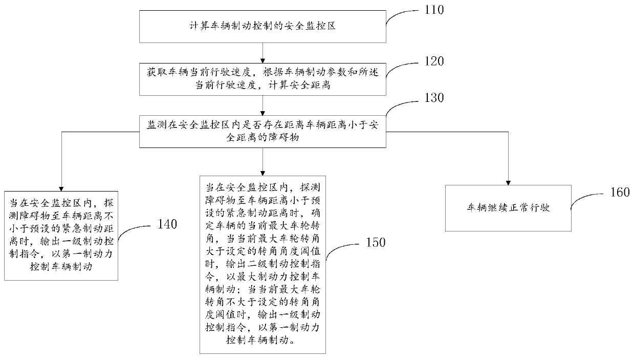
[0037] The brake control method provided by the present invention, its execution method is as follows image 3 As shown, it mainly includes the following steps:

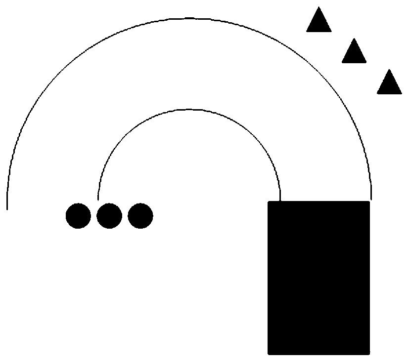
[0038] Step 110, calculating the safety monitoring area for vehicle braking control;

[0039] According to the existing kinematic bicycle model in the industry, assuming that the vehicle is shaped like a bicycle, the entire control quantity can be simplified as (a,δ f ), where a is the acceleration of the vehicle, stepping on the gas pedal means positive acceleration, and stepping on the brake pedal means negative acceleration. δ f is ou...


PUM


Abstract

The embodiment of the invention relates to a brake control method for an unmanned vehicle. The brake control method for the unmanned vehicle comprises the following steps: calculating a safety monitoring and control area of vehicle brake control; obtaining the current running speed of the vehicle, and calculating a safety distance according to vehicle brake parameters and the current running speed; monitoring whether an obstacle having a distance which is less than the safety distance, away from the vehicle, exists in the safety monitoring and control area or not; while detecting that the distance between the obstacle and the vehicle is not less than a preset emergency brake distance in the safety monitoring and control area, outputting a first-stage brake control instruction, and controlling the vehicle to brake by a first brake force; while detecting that the distance between the obstacle and the vehicle is less than the preset emergency brake distance in the safety monitoring and control area, determining the current maximum vehicle wheel rotation angle of the vehicle, outputting a second-stage brake control instruction when the current maximum vehicle wheel rotation angle is greater than a set rotation angle threshold value, and controlling the vehicle to brake by the maximum brake force; and outputting a first-stage brake control instruction when the current maximum vehicle wheel rotation angle is not greater than the set rotation angle threshold value, and controlling the vehicle to brake by the first brake force.

Description

technical field [0001] The invention relates to the technical field of automatic driving control, in particular to a braking control method for unmanned vehicles. Background technique [0002] Braking control is a very key technical element of unmanned driving technology. The emergency braking algorithm of unmanned vehicles requires the cooperation of the perception module and the control module. The perception module is responsible for detecting obstacles and classifying obstacles, and then performing coordinate transformation , giving the coordinates, velocity and obstacle type of the obstacle in the car body coordinate system. [0003] At present, the emergency braking algorithm in the field of unmanned driving generally only considers whether there is an obstacle in the dangerous area directly in front or behind the vehicle, and judges whether the coordinates of the obstacle in the vehicle body coordinate system are within the dangerous range, so as to obtain whether the...

Claims


Application Information

Patent Timeline
IPC IPC(8): B60W30/09
CPCB60W30/09B60W2554/00
Inventor 郭小军颜波张放李晓飞霍舒豪王肖张德兆
Owner BEIJING ZHIXINGZHE TECH CO LTD
Features
  • Generate Ideas
  • Intellectual Property
  • Life Sciences
  • Materials
  • Tech Scout
  • Unparalleled Data Quality
  • Higher Quality Content
  • 60% Fewer Hallucinations
Learn More